
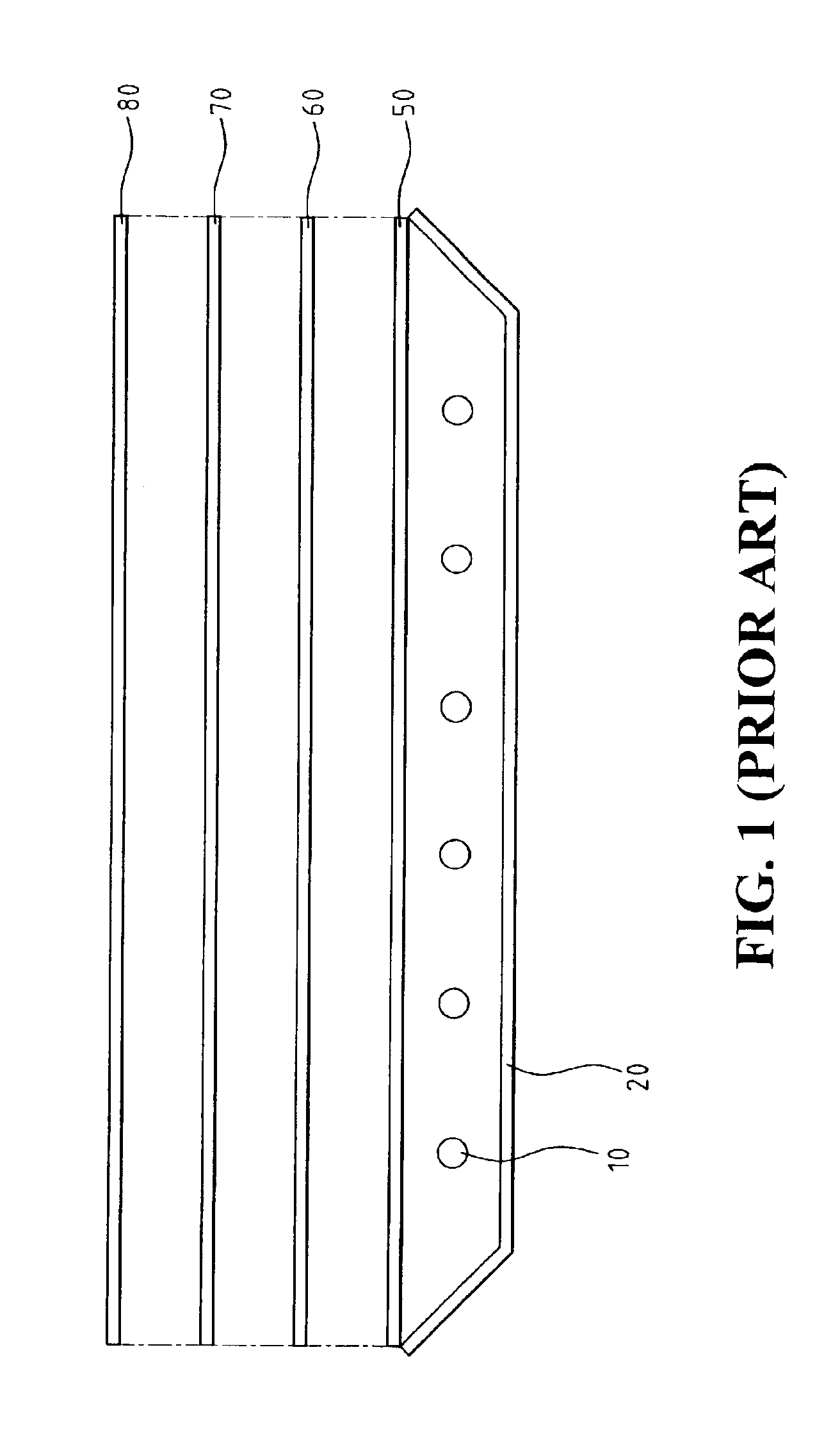
Direct-lighting type back light unit

Inactive Publication Date: 2005-07-05
AU OPTRONICS CORP
View PDF8 Cites 15 Cited by
  • Summary
  • Abstract
  • Description
  • Claims
  • Application Information

AI Technical Summary

Benefits of technology

[0009]A primary object of the present invention is to provide a back light unit that allows for good uniformity, good luminance, and thin thickness without using printing ink.
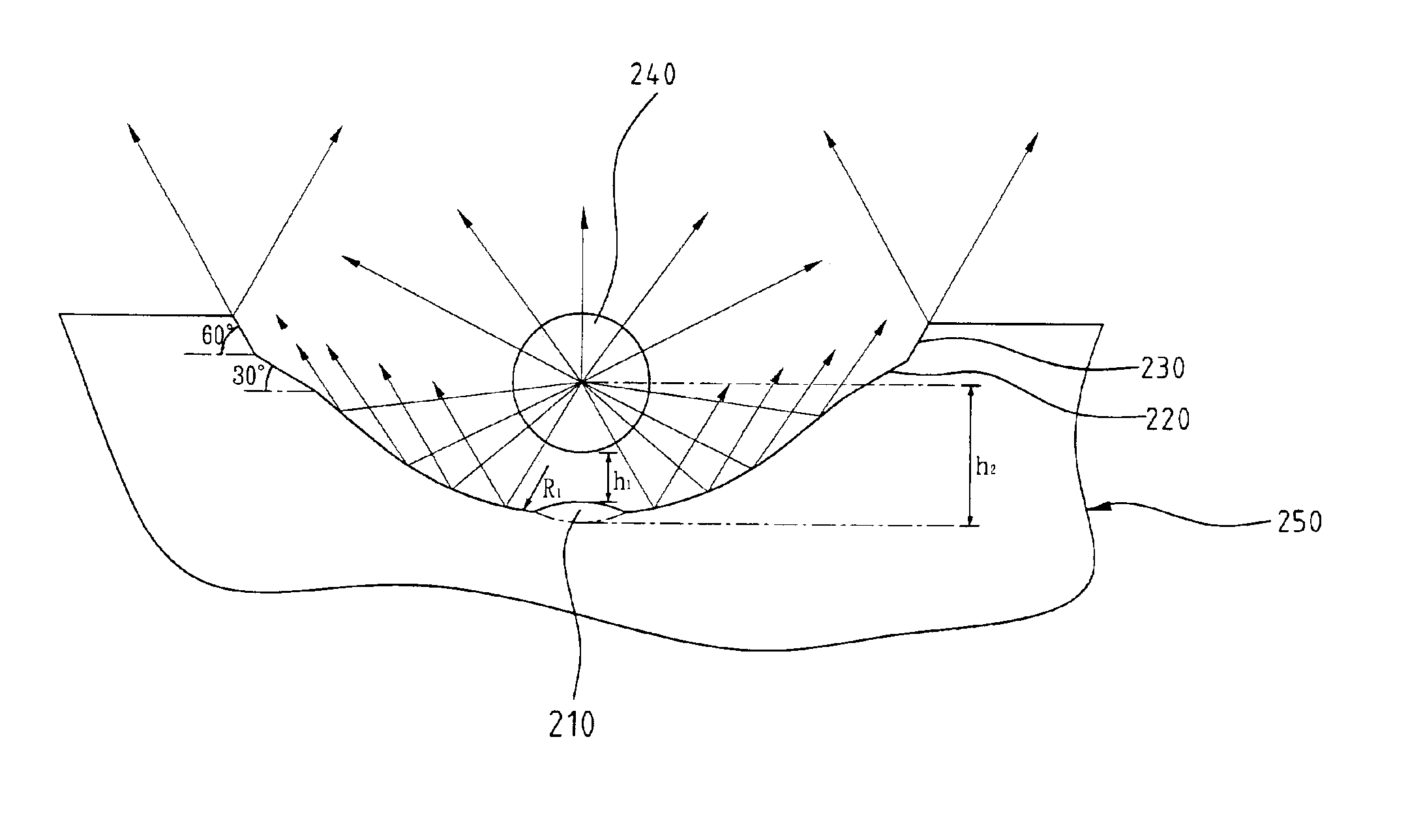
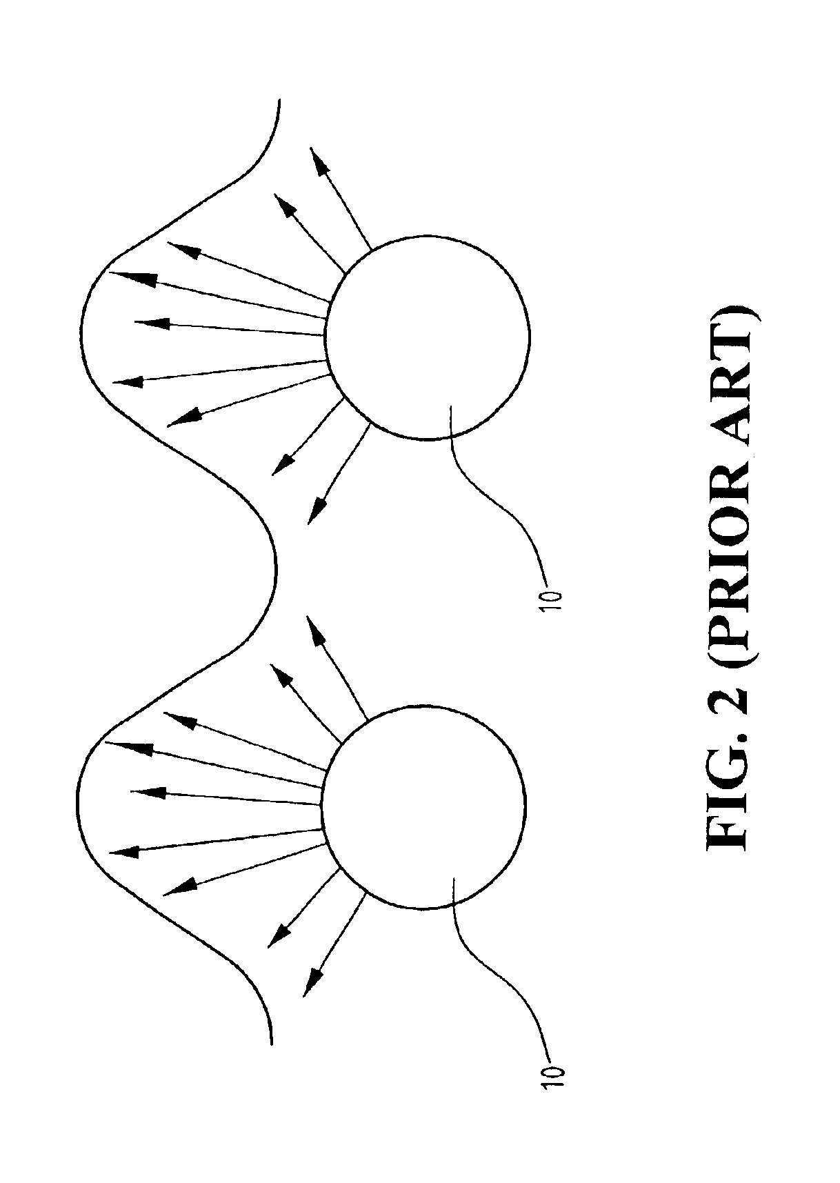
[0010]It is another object of the present invention to provide a reflector for a back light unit having curved reflecting surface to control the reflecting angle of the light, which enables the energy produced by the light source to be distributed uniformly to increase the uniformity of the display screen.
[0011]It is another object of the present invention to provide a reflector for a back light unit having a curved reflecting surface to control the reflecting angle of the light and to reduce the defect of the light energy absorbed between lamps, whereby the distance between the light source and the diffusing plate can be reduced to reduce the thickness of the back light unit, and the luminance of the display screen can be raised.
[0012]It is another object of the present invention to provide a reflector for a back light unit having a curved reflecting surface to control the reflecting angle of the light, which enables the energy produced by the light source to be distributed uniformly to meet the requirement of uniformity of the display screen without using printing ink.
[0014]It is another object of the present invention to provide a non-printed type guiding plate for a back light unit which allows for omission of the conventional diffusing plate thereby reducing the thickness and weight of the back light unit.

Problems solved by technology

However, it suffers from increased thickness and decreased luminance due to the space exiting between the diffusing plate and light source.
Further, the ink may get aged, making back light unit become yellowish.

Method used


Image

  • Direct-lighting type back light unit
  • Direct-lighting type back light unit
  • Direct-lighting type back light unit

Examples


Embodiment Construction

[0026]Some embodiments of the invention will now be described in greater detail. Nevertheless, it should be recognized that the present invention can be practiced in a wide range of other embodiments besides those explicitly described, and the scope of the present invention is expressly not limited except as specified in the accompanying claims.

[0027]Referring to FIGS. 4-6, a light source 240 is disposed in a curved reflecting recess defined in a reflecting plate 250. The light source 240 may comprise a tubular lamp having a diameter Φ of about 2.6 mm. The reflecting recess partially surrounds the light source 240. A first, convex reflecting surface 210 is formed at a center part of the reflecting recess. The first surface 210 has a radius of curvature about 2-3 times of the diameter of the lamp 240 (namely Φ). The left edge part of the reflecting recess forms a second reflecting surface 220, which is inclined with respect to a horizontal surface and has an inclined angle from 20 to...


PUM


Abstract

A direct-lighting type back light unit includes a plurality of light sources for emitting light outward; a reflecting plate defining a plurality of curved reflecting recesses in which the light sources are respectively arranged. Each recess forms a first convex reflecting surface at a center of the recess, a second inclined reflecting surface formed at an edge of the recess and a third inclined reflecting surface formed at the edge and extending from the second reflecting surface.

Description

FIELD OF THE INVENTION[0001]The present invention relates to a direct-lighting type back light unit for liquid crystal display (LCD) device, more particularly to a direct-lighting type back light unit having a reflector with a plurality of light sources and a plurality of reflecting surfaces corresponding to the number of the light sources.BACKGROUND OF THE INVENTION[0002]Recently, the integration of device components in a computer is getting denser and, therefore, the requirement to the components of the computer is that they have to be lighter, thinner, shorter and less power consumption. Comparing to the other display devices, such as cathode ray tube (CRT), the LCD is a small-sized device and has a low power consumption. In addiction to a liquid crystal screen, the LCD requires a light source because the liquid crystal is not a self-luminous substance.[0003]Currently, lamps, such as CCLF (Cold Cathode Fluorescent Lamp) and HCFL (Hot Cathode Fluorescent Lamp), have been used as a...

Claims


Application Information

Patent Timeline
IPC IPC(8): F21V7/09F21V7/00F21V13/00F21V13/04G02F1/1335G02F1/13G02F1/13357
CPCF21V7/005F21V7/09F21V13/04G02B6/0031G02F1/133604G02F1/133605G02F1/133606G02B6/0021G02B6/0068G02B6/0071
Inventor HO, YI-CHUN
Owner AU OPTRONICS CORP
Learn More