
Method and apparatus for pilot fuel introduction and controlling combustion in gaseous-fuelled internal combustion engine

a technology of gaseous fuel and internal combustion engine, which is applied in the direction of fuel supply apparatus, drinking water installation, and fluid removal, etc., can solve the problems of affecting the efficiency of the engine, and the rapid release of fuel energy, so as to improve efficiency and reduce emissions.

Inactive Publication Date: 2005-07-05
WESTPORT POWER
View PDF18 Cites 76 Cited by
  • Summary
  • Abstract
  • Description
  • Claims
  • Application Information

AI Technical Summary

Benefits of technology

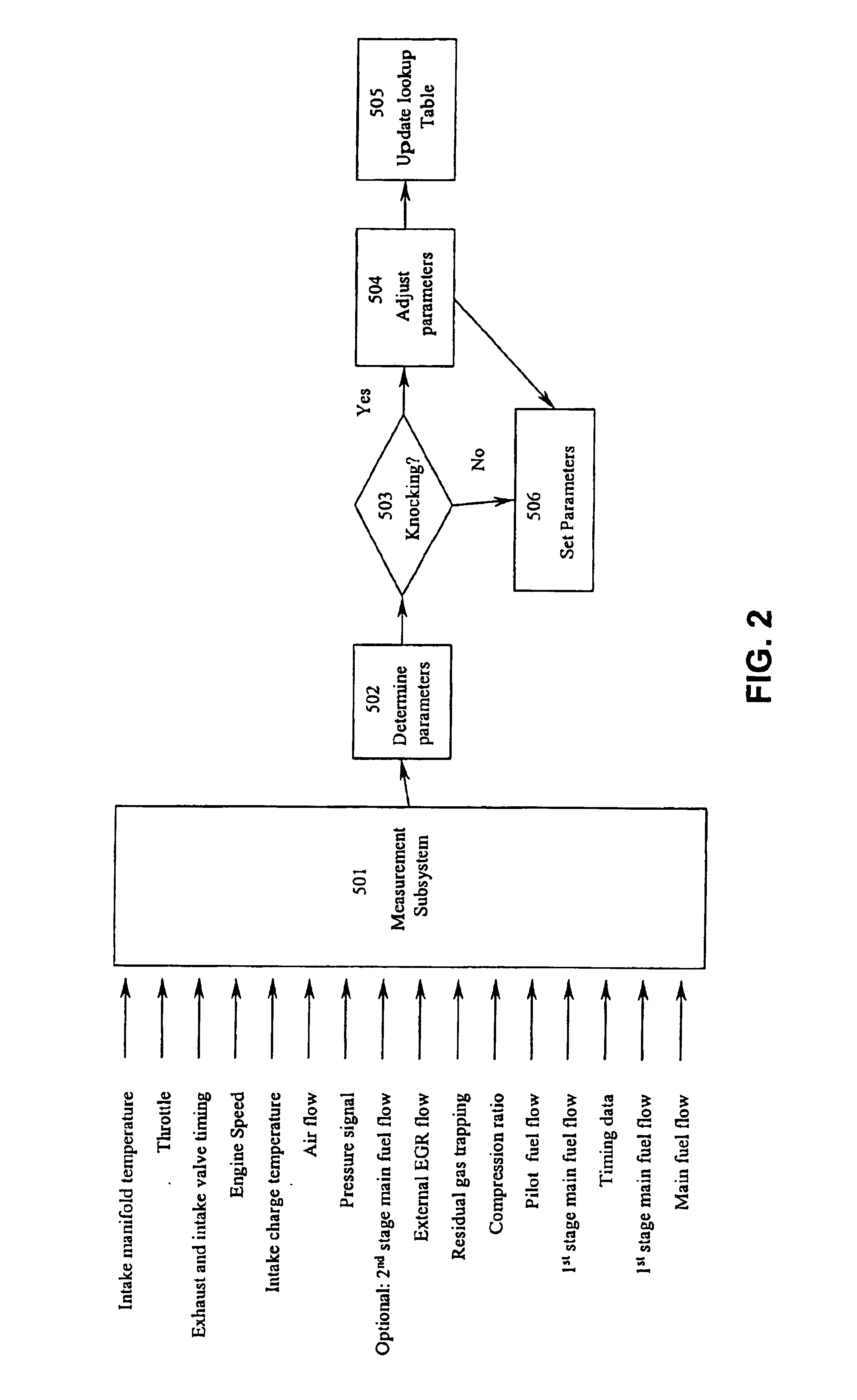
[0028](d) introducing a pilot fuel quantity of the pilot fuel at the pilot fuel timing into the cylinder so that it ignites when the piston is at or near top dead centre of the compression stroke, the pilot timing avoiding a excessive knocking range during a compression stroke of the engine;wherein the first quantity, the pilot fuel quantity and the pilot fuel timing are controllable in response to engine load or engine speed, the first quantity forming a premixed charge of fuel and air prior to ignition of the pilot fuel.
[0031]For improved efficiency and reduced emissions, the mixed combustion mode is preferably a homogeneous charge compression ignition mode.
[0046](d) a pilot fuel injection valve controlled by the electronic control unit to introduce the pilot fuel into the cylinder at times and in quantities determined by the electronic control unit with the predetermined operating modes and the set of load conditions;The predetermined operating mode comprises a two stage introduction of fuel into the cylinder. A first portion of the main fuel is introduced in a first stage to provide for a premixed fuel / air charge prior to combustion of the pilot fuel and the pilot fuel is introduced in a second stage, the controller and the pilot fuel injection valve capable of detecting and avoid an excessive knocking range for introduction of the pilot fuel.

Problems solved by technology

One disadvantage is encountered at high load engine operating conditions, when the elevated temperature and pressure in the piston cylinder during the compression stroke makes the air / natural gas mixture susceptible to “knocking”.
Knocking leads to a rapid rate of fuel energy release that can damage engines.
These measures, however, cause a corresponding reduction in the engine's cycle efficiency (that is, not as much power is available from each piston stroke).
A second disadvantage of known dual fuel methods is that under low load engine operating conditions, the mixture of fuel and air becomes too lean to support stable premixed combustion and results in incomplete combustion or misfiring.
The intake air flow can be throttled to maintain a mixture that can sustain premixed combustion, but throttling adversely affects engine efficiency.
In a flame propagation combustion mode, the rate of combustion is limited by the transfer of the unburned mixture of fuel and air into the flame reaction zone.
For example, a fuel / air equivalence ratio of between 0.1 to 0.5 can burn in a HCCI combustion mode, whereas under the same conditions, in a propagation combustion mode combustion would be unstable, leading to misfire or partial burn.
With a HCCI engine the rate of combustion is potentially very rapid, resulting in high engine cycle efficiencies (relative to a conventional diesel-fuelled engine).
However, a disadvantage of HCCI combustion is the lack of direct control over the start and rate of combustion because only indirect control methods are available.
Another disadvantage of HCCI combustion is that at high load conditions, the higher fuel / air ratios result in HCCI combustion rates which can cause engine damage by combusting too rapidly, or by the rate of combustion causing very high in-cylinder pressures.

Method used


Image

  • Method and apparatus for pilot fuel introduction and controlling combustion in gaseous-fuelled internal combustion engine
  • Method and apparatus for pilot fuel introduction and controlling combustion in gaseous-fuelled internal combustion engine
  • Method and apparatus for pilot fuel introduction and controlling combustion in gaseous-fuelled internal combustion engine

Examples


Embodiment Construction

)

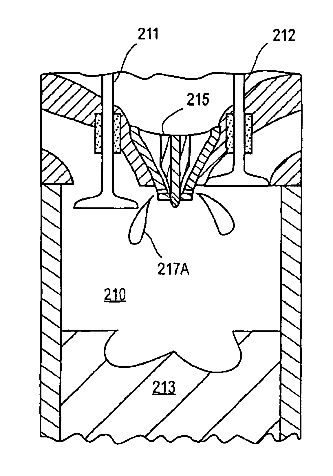
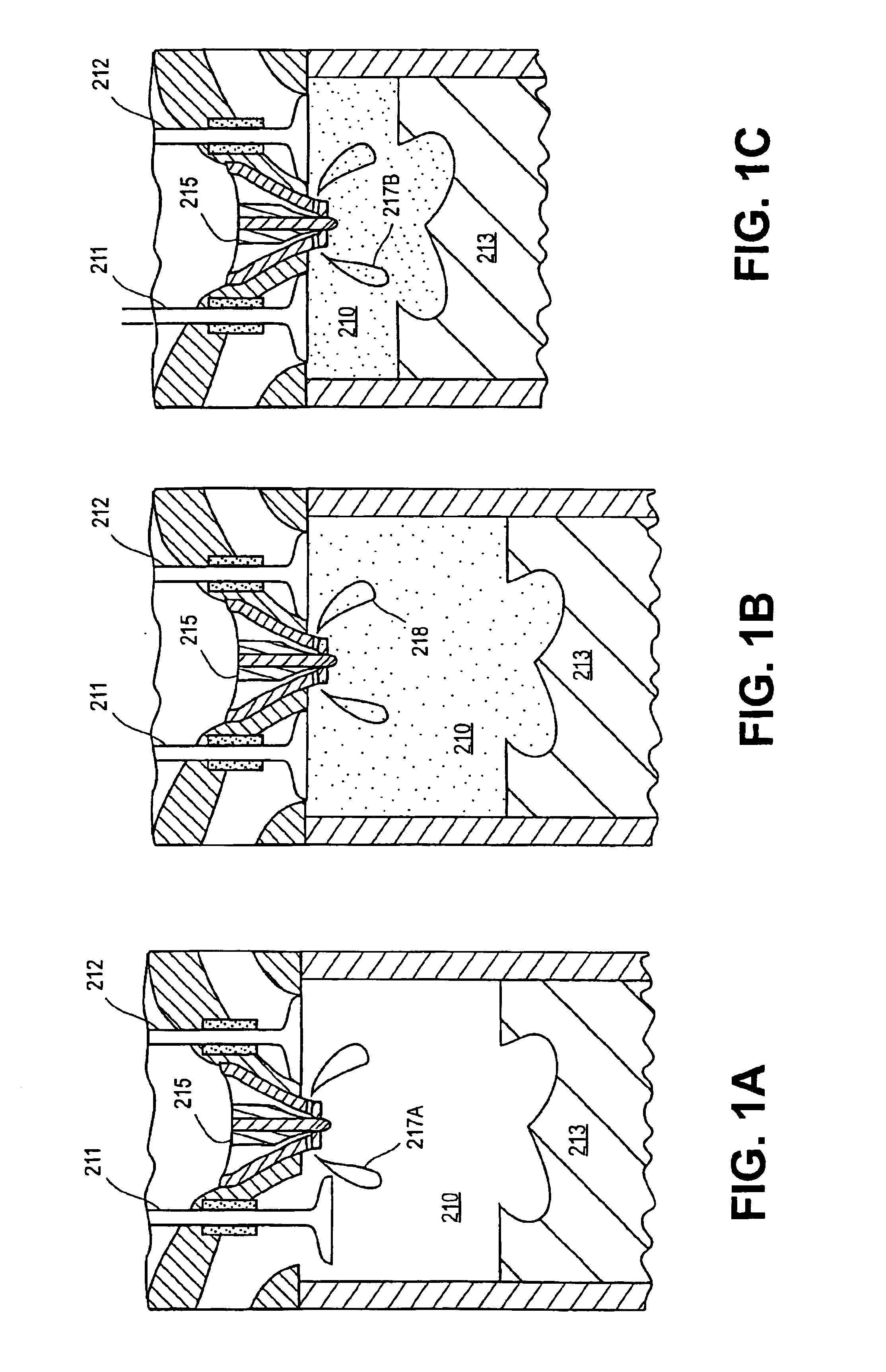
[0053]In a preferred method, fuel is injected into the cylinder of a four-stroke internal combustion engine having at least one reciprocating piston and a crankshaft associated with the piston. In this disclosure, the position of the piston within the cylinder is described with reference to crank angle degrees before or after top dead center (TDC). The piston is at TDC is when the piston has reached the end of an upward stroke and is about to begin a downward stroke (that is, the point when the piston is closest to the cylinder head).

[0054]The method involves a main fuel, which is preferably a gaseous fuel such as, for example, natural gas, propane, bio-gas, landfill gas or hydrogen gas. The method can further comprise the use of an ignition source to control the combustion timing of the main fuel. The ignition source can be, for example, a pilot fuel that auto-ignites more readily than the main fuel, a hot surface ignition source, such as a glow plug, a spark plug, or other known ...


PUM


Abstract

A method and apparatus for introducing pilot fuel into a piston cylinder of an operating gaseous fuelled internal combustion engine monitoring a set of engine parameters, determining engine load and engine speed from the set of engine parameters, introducing a first portion of the gaseous fuel into the cylinder where the first portion of gaseous fuel forms a substantially homogeneous mixture comprising gaseous fuel and air prior to combustion, and introducing a pilot fuel to avoid a excessive knocking range for the engine. A second quantity of gaseous fuel can also be added to burn in a substantially diffusion combustion mode.

Description

CROSS-REFERENCE TO RELATED APPLICATION(S)[0001]This application is a continuation-in-part of U.S. patent application Ser. No. 09 / 748,547 filed Dec. 26, 2000, now U.S. Pat. No. 6,640,773, issued Nov. 4, 2003, entitled “Method and Apparatus for Gaseous Fuel Introduction and Controlling Combustion in an Internal Combustion Engine”. The '547 application is hereby incorporated by reference herein in its entirety.FIELD OF THE INVENTION[0002]The present invention relates to a method and apparatus for introducing pilot fuel into the cylinder of a gaseous-fuelled internal combustion engine. More specifically, the present invention relates to a method of, and apparatus for, the introduction of gaseous fuel into the engine's cylinder and the timing of pilot fuel introduction for igniting the gaseous fuel and controlling the combustion mode of the gaseous fuel introduced.BACKGROUND OF THE INVENTION[0003]The internal combustion engine industry is under ever increasing pressure to reduce pollutio...

Claims


Application Information

Patent Timeline
Patent Type & Authority Patents(United States)
IPC IPC(8): F02D19/02F02D41/00F02D19/00F02B23/02F02B1/12F02D41/40F02B7/00F02B43/00F02B1/00F02B23/06F02D41/30F02M21/02F02B7/08F02B3/00F02B3/06F02B75/02
CPCF02B1/12F02B7/08F02B23/0672F02B43/00F02D35/027F02D41/0027F02D41/3047F02D41/402F02D41/403F02D19/061F02D19/0689F02D19/0694F02D19/10Y02T10/36F02B23/0621F02B23/0669F02B2075/025F02B2275/14F02D41/0025F02D2041/389Y02T10/125Y02T10/128Y02T10/44Y02T10/123Y02T10/32F02M21/0206F02M21/0212F02M21/0215F02B3/06F02D35/023F02D35/028Y02T10/12Y02T10/30Y02T10/40
Inventor ANCIMER, RICHARDTANIN, KONSTANTIN V.
Owner WESTPORT POWER
Learn More