
Loader-type heavy-construction machine

a construction machine and loader technology, applied in mechanical machines/dredgers, position/direction control, lifting devices, etc., can solve the problems of mechanical action incompatible with the hydraulic directional control valve, mechanical complexity, and difficulty in setting up, so as to improve the comfort of operation control

Inactive Publication Date: 2005-07-05
VOLVO CONSTR EQUIP HLDG SWEDEN AB
View PDF17 Cites 8 Cited by
  • Summary
  • Abstract
  • Description
  • Claims
  • Application Information

AI Technical Summary

Benefits of technology

"The invention is about a construction engineering machine called a loader. This machine has a chassis and work equipment including two parallel arms, a bucket, and link rods. It also has a bucket actuator that can be controlled to move the bucket in different directions. The invention is about adding a hydraulic control circuit that allows the bucket actuator to be controlled by a hydraulic manipulator. This circuit also includes a cam mechanism that generates an additional control pressure based on the position of the bucket. This additional pressure prevents the bucket from tilting backward during operation. Overall, this invention improves the stability and comfort of controlling the loader's operations."

Problems solved by technology

It will be appreciated that this solution has certain disadvantages, particularly the fact that it acts directly on the spool of the directional control valve, which means that it has a reaction on the control manipulator on which the driver acts.
In other words, this automatic correction generates resistance in the movement of the manipulator and this is felt by the driver and may prove disagreeable.
Furthermore, such a correction by mechanical action on the hydraulic directional control valve is incompatible with the use of a hydraulic manipulator which acts on the directional control valve by applying a pressure according to the position of the manipulator.
Such a solution is mechanically complicated and it is particularly difficult to set up.

Method used


Image

  • Loader-type heavy-construction machine
  • Loader-type heavy-construction machine
  • Loader-type heavy-construction machine

Examples


Embodiment Construction

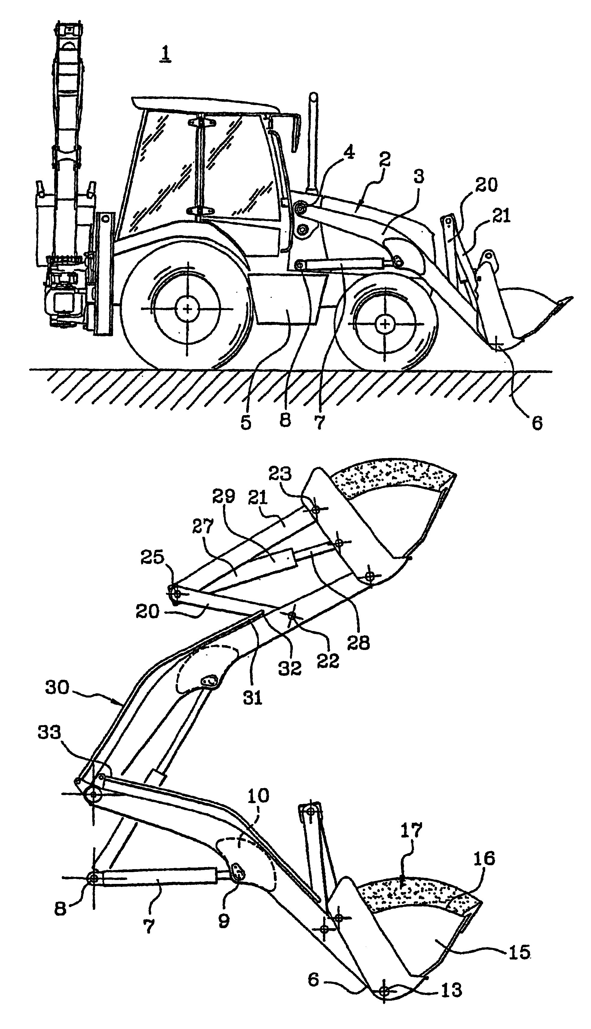
[0033]As already stated, the invention relates to a construction engineering machine having a “loader” and, for example, a “loader / shovel” function as illustrated in FIG. 1. In its front part, this machine (1) comprises work equipment (2) allowing it to act as a loader. This work equipment (2) mainly comprises two arms (3) situated one on each side of the machine. Via their rear ends (4) these arms (3) are articulated to the chassis (5). These arms (3) have a slightly curved shape so that their front ends (6) are roughly at ground level when the arms (3) are in the lowermost position. These arms (3) can be moved under the action of two arm actuators (7) also situated one on each side of the chassis (5). These actuators (7) are articulated by one end (8) to the chassis and by their opposite end (9) to the main arms (3) roughly at the middle (10) thereof.

[0034]At their front ends (6), the main arms (3) take a bucket (15). This bucket (15) is articulated with respect to the arms (3) so...


PUM


Abstract

A loader-type heavy construction machine has a chassis and work equipment. The work equipment includes two parallel arms articulated relative to the frame, a bucket articulated relative to the arms, a set of link rods forming, with a portion of the bucket and of the arms, a deformable parallelogram, and a bucket actuator capable of being controlled to cause deformation of the deformable parallelogram so as to orient the bucket with respect to the arms. A cam is moved by a connecting bar connected at one end to the deformable parallelogram so that the position of the cam is dependent on the orientation of the bucket with respect to the chassis. The cam interfaces with an hydraulic circuit to ensure that the bucket is maintained in a position preventing it from accidentally tipping over backwards, regardless of commands exerted on an hydraulic manipulator by a driver of the machine.

Description

CROSS-REFERENCE TO RELATED APPLICATIONS[0001]This application is a continuation of international application PCT / FR 02 / 00976 filed Mar. 20, 2002 and published, in French, as WO 02 / 081828 on Oct. 17, 2002, and claims priority from Application No. 01.03858 filed Mar. 22, 2001 in France.TECHNICAL FIELD[0002]The invention relates to the field of construction engineering machines, more particularly machines of the loader type. It is aimed more specifically at a device that automatically corrects the orientation of the bucket during the various loading operations.PRIOR ART[0003]In general, a construction engineering machine that allows material laid out on the ground to be picked up and tipped out into a skip or a truck, or vice versa, is known as “loader”. A loader therefore comprises, in a known way, a chassis and special work equipment. This work equipment generally includes two parallel arms articulated with respect to the chassis. These arms can be raised under the action of actuator...

Claims


Application Information

Patent Timeline
Patent Type & Authority Patents(United States)
IPC IPC(8): E02F3/43E02F3/42
CPCE02F3/432E02F3/433
Inventor CHARLES, GEORGES
Owner VOLVO CONSTR EQUIP HLDG SWEDEN AB
Learn More