Fuel cell system
a fuel cell and power supply technology, applied in the field of power supplies, can solve problems such as equipment damage, loss of use or data, and/or productivity loss, and achieve the effects of improving efficiency, reducing costs, and improving efficiency
- Summary
- Abstract
- Description
- Claims
- Application Information
AI Technical Summary
Benefits of technology
Problems solved by technology
Method used
Image
Examples
example 1
Fuel Cell System For Powering a Lawnmower
[0047]An exemplary fuel cell system suitable for use in powering a lawnmower can comprise two fuel cell stacks, a tank for zinc fuel and electrolyte, a pump for circulating zinc fuel pellets and KOH electrolyte between the fuel cell stacks and the zinc / electrolyte tank, an air blower for each cell stack, a heat exchanger for each cell stack, and electronics for electrical current control.
[0048]Each fuel cell stack can comprise twenty cells connected electrically in series, where fuel and electrolyte can be continuously recirculated through the pump, the cell stacks and the electrolyte tank. The maximum combined output power of an exemplary set of such stacks can be about 5.3 kW. Zinc fuel pellets and KOH electrolyte can be stored in the electrolyte tank that is mounted under the fuel cell stacks. The tank capacity of an illustrative electrolyte tank can be about 45 liters and can contain sufficient zinc to produce about 7 kWh of electricity.
[...
example 2
Fuel Cell System For Powering a Personal Power Source
[0052]An exemplary fuel cell system suitable for use in powering a personal power source (e.g., a power source suitable for powering a variety of loads can comprise a fuel stack, a tank for zinc fuel and electrolyte, a pump for circulating zinc fuel pellets and KOH electrolyte between the fuel cell stacks and the electrolyte tank, an air blower, a heat exchanger, and electronics for electrical current control.
[0053]Each fuel cell stack can comprise twenty cells connected electrically in series, where fuel and electrolyte can be continuously recirculated through the pump, the cell stacks and the electrolyte tank. The maximum combined output power of an exemplary set of such stacks can be about 2.6 kW. Zinc fuel pellets and KOH electrolyte can be stored in the electrolyte tank that is mounted under the fuel cell stacks. The tank capacity of an illustrative electrolyte tank can be about 5.5 liters and can contain sufficient zinc to p...
example 3
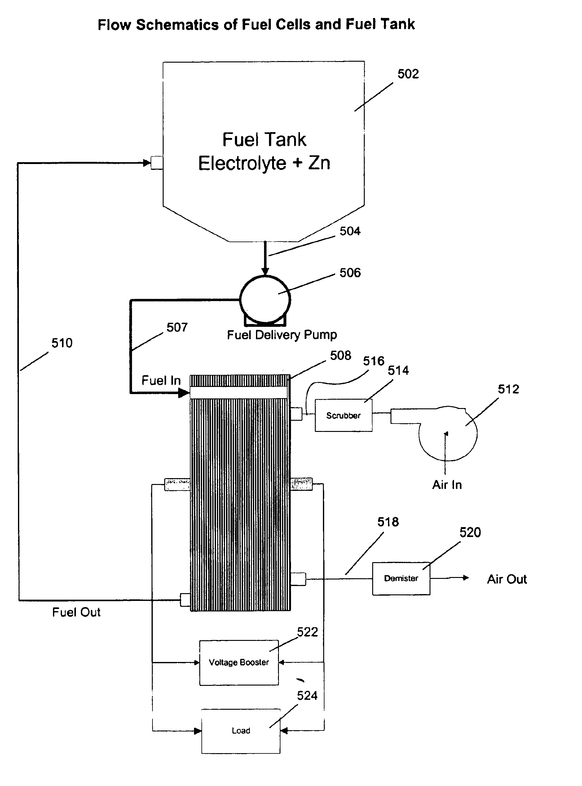
[0057]With reference to FIG. 2, zinc pellets and KOH electrolyte can be contained within the fuel tank (electrolyte+zinc) 502. These particles can be initially at rest until such time as they are picked up in the stream of flowing KOH electrolyte, Q1, identified with numeral 504. The stream of KOH electrolyte and zinc pellets can be sucked from the tank and into the fuel delivery pump 506. From the fuel delivery pump 506, the stream can enter a pipe that directs them toward the fuel cell stack 508 through flow path 507. On entering the fuel cell stack 508, the electrolyte and pellets flow stream can first encounter a flow distribution manifold (not illustrated; exemplary manifold suitable for use found in U.S. patent application Ser. No. ______ To Be Determined, entitled “MANIFOLD FOR FUEL CELL SYSTEM,”, filed on even date herewith, and previously incorporated herein by this reference) that can distribute electrolyte and zinc pellets substantially uniformly ...
PUM
| Property | Measurement | Unit |
|---|---|---|
| electrochemical potential | aaaaa | aaaaa |
| pressure | aaaaa | aaaaa |
| volumes | aaaaa | aaaaa |
Abstract
Description
Claims
Application Information
 - R&D
- Intellectual Property
- Life Sciences
- Materials
- Tech Scout
- Unparalleled Data Quality
- Higher Quality Content
- 60% Fewer Hallucinations
Browse by: Latest US Patents, China's latest patents, Technical Efficacy Thesaurus, Application Domain, Technology Topic, Popular Technical Reports.
© 2025 PatSnap. All rights reserved.Legal|Privacy policy|Modern Slavery Act Transparency Statement|Sitemap|About US| Contact US: help@patsnap.com


