
Method and apparatus for associating selected circuit instances and for performing a group operation thereon

a circuit design and database technology, applied in the field of method and apparatus for manipulating a group of instances of a circuit design database, can solve the problems of prior art floorplanning tools suffering from a number of limitations, and unable to achieve optimal design solutions

Inactive Publication Date: 2005-06-21
UNISYS CORP
View PDF38 Cites 54 Cited by
  • Summary
  • Abstract
  • Description
  • Claims
  • Application Information

AI Technical Summary

Benefits of technology

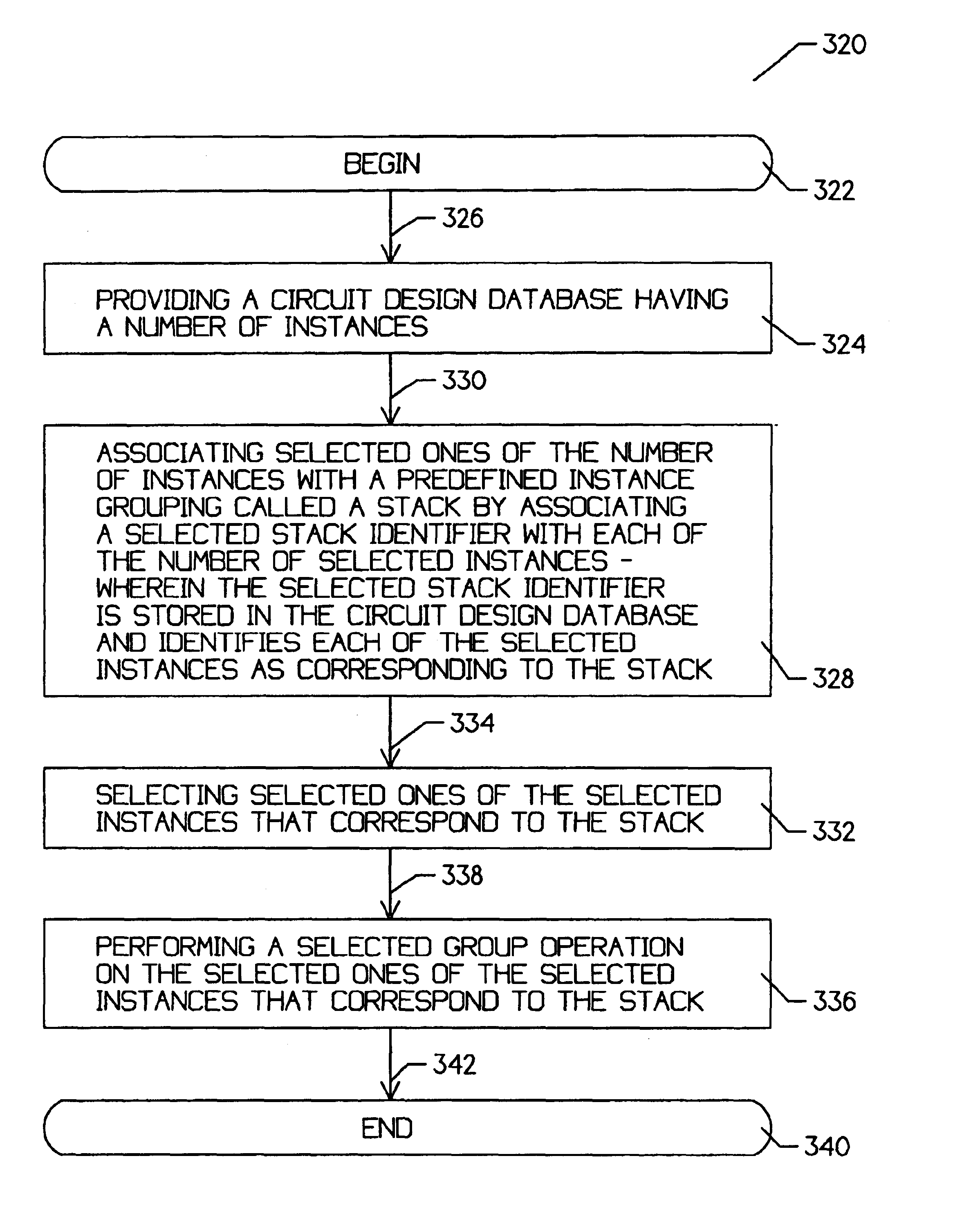
[0027]In an exemplary embodiment, the circuit design database may include a stack identifier that may identify the association of the selected instances with a selected stack. The database editor tool may then read the circuit design database and identify which of the instances are associated with each of a number of stacks. It is contemplated that the database editor may then perform a group operation on all or some of the instances associated with a selected stack. This may improve the efficiency and accuracy of manual manipulation of circuit instances, particularly since all of the cells associated with a particular stack may be manipulated at the same time.
[0030]In contrast, a floorplanning tool of the present invention may understand the stack identifiers provided in the circuit design database, and may provide an efficient way to manipulate and place the instances associated therewith. For example, any cell manipulation operation that can be used to move, place, edit, etc. a single cell, may also be used to manipulate all instances associated with a stack. That is, all instances associated with a stack may be placed, moved, unplaced, abutted, redrawn, aligned, connected, mirrored, etc., in a similar manner as a single cell may be manipulated.

Problems solved by technology

Typically, the logic design synthesis software is executed many times during the integrated circuit design process, because errors may be detected during the simulation and testing phases of the design cycle and then fixed in the behavioral description.
It is noted, however, that this action typically affects the component and net names generated by the logic synthesis tool.
If errors are found or the resulting functionality is unacceptable, the designer modifies the behavior description as needed.
Because automatic placement tools may not yield an optimal design solution, particularly for high performance designs that have strict timing and physical requirements, circuit designers often manually place critical circuit objects (e.g. cells or regions) within the boundary of the integrated circuit.
These prior art floorplanning tools suffer from a number of limitations, some of which are described below.
First, while some floorplanning tools may allow some editing operations to be performed on user-defined groups of objects, the circuit designer typically must select the objects using a pointing device within the floorplanning window (for example, selecting all objects within a selected area in the floorplanning window).
The prior art floorplanning tools typically do not allow groups of instances to be defined as a group prior to entering the floorplanning tool.
This provides a major limitation since many group operations are performed on groups of objects that may not be readily identifiable by the circuit designer from within the floorplanning tool.
Since large contexts often contain thousands of regions and / or cells, the physical window may provide little utility during the placement process.
Thus, to place a desired group of objects in a typical prior art floorplanning tool, the circuit designer must execute a series of time-consuming steps.
Largely because of this tedious process, circuit designers often decide to not perform manual placement, if at all possible.

Method used


Image

  • Method and apparatus for associating selected circuit instances and for performing a group operation thereon
  • Method and apparatus for associating selected circuit instances and for performing a group operation thereon
  • Method and apparatus for associating selected circuit instances and for performing a group operation thereon

Examples


Embodiment Construction

[0052]The detailed descriptions which follow are presented largely in terms of algorithms and symbolic representations of operations on data bits within a computer memory. These algorithmic descriptions and representations are the means used by those skilled in the data processing arts to most effectively convey the substance of their work to others skilled in the art.

[0053]An algorithm is here, generally, conceived to be a self-consistent sequence of steps leading to a desired result. These steps are those requiring physical manipulations of physical quantities. Usually, though not necessarily, these quantities take the form of electrical or magnetic signals capable of being stored, transferred, combined, compared, and otherwise manipulated. It proves convenient at times, principally for reasons of common usage, to refer to these signals as bits, values, elements, symbols, characters, terms, numbers or the like. It should be kept in mind, however, that all of these and similar term...


PUM


Abstract

A method and apparatus for associating selected circuit instances, and for allowing a later group manipulation thereof. Prior to entering a database editor tool, selected instances may be associated with one another, and the association may be recorded in the circuit design database. The database editor tool may then read the circuit design database and identify the selected instances and the association therebetween. The associated instances may be called a group, or preferably a stack. The database editor tool may then perform a group operation on the instances associated with the stack.

Description

CROSS REFERENCE TO CO-PENDING APPLICATIONS[0001]The present application is related to U.S. patent application Ser. No. 08 / 789,025, filed Jan. 27, 1997, entitled “Method and Apparatus for Efficiently Viewing a Number of Selected Components Using a Database Editor Tool”, U.S. patent application Ser. No. 08 / 789 / 026, filed Jan. 27, 1997, entitled “Method and Apparatus for Selecting Components Within a Circuit Design Database”, U.S. patent application Ser. No. 08 / 789,027, filed Jan. 27, 1997, entitled “Method and Apparatus for Selectively Viewing Nets Within a Database Editor Tool”, U.S. patent application Ser. No. 08 / 789,024, filed Jan. 27, 1997, entitled “Method and Apparatus for Identifying Physical Errors in a Placement Database”, U.S. patent application Ser. No. 08 / 789,029, filed Jan. 27, 1997, entitled “Method and Apparatus for Using a Placement Tool to Manipulate Cell Substitution Lists”, U.S. patent application Ser. No. 08 / 598,506, filed Feb. 7, 1996 entitled “Method and Apparatu...

Claims


Application Information

Patent Timeline
IPC IPC(8): G06F9/45G06F17/50G06F9/455
CPCG06F17/505G06F30/327
Inventor AUBEL, MARK D.KERZMAN, JOSEPH P.NEAD, JAMES M.REZEK, JAMES E.
Owner UNISYS CORP
Learn More