Eureka AIR delivers breakthrough ideas for toughest innovation challenges, trusted by R&D personnel around the world.

Composite dielectric material, composite dielectric substrate, prepreg, coated metal foil, molded sheet, composite magnetic substrate, substrate, double side metal foil-clad substrate, flame retardant substrate, polyvinylbenzyl ether resin composition, thermosettin

a technology of thermosettin and dielectric substrate, which is applied in the direction of printed inductor incorporation, granular delivery, special tyres, etc., can solve the problems of high dielectric constant of compound in high-frequency band, difficulty in drilling and machineing laminates, and low dielectric constant , the effect of low dissipation factor

Inactive Publication Date: 2005-06-21
TDK CORPARATION
View PDF14 Cites 62 Cited by
  • Summary
  • Abstract
  • Description
  • Claims
  • Application Information

AI Technical Summary

Benefits of technology

[0031]A fourth object of the invention is to provide (1) a composite magnetic substrate and a prepreg having a low dielectric constant and low dissipation factor; (2) a composite magnetic substrate and a prepreg having high heat resistance, typically a high glass transition temperature and high decomposition initiation temperature; (3) a composite magnetic substrate and a prepreg having a low water pickup and a minimized change of dielectric constant and dissipation factor; (4) a composite magnetic substrate and a prepreg which have close adhesion to a metal foil such as copper foil and a reduced thickness, and can be manufactured by a conventional substrate manufacturing process; (5) a composite magnetic substrate and a prepreg having a constant dielectric constant and dissipation factor up to a frequency band of the order of gigahertz; and (6) a composite magnetic substrate and a prepreg having minimized temperature dependency of dielectric constant and dissipation factor.
[0032]A fifth object of the invention is to provide a flame retardant substrate and prepreg having improved flame retardance, and good electrical characteristics at high frequencies for use in electronic parts and circuit substrates.
[0033]A sixth object of the invention is to provide a thermosetting polyvinylbenzyl ether resin composition which in the cured state exhibits dielectric characteristics that are satisfactory and constant over a wide frequency region and less dependent on temperature and moisture pickup, and maintains unchanged the physical properties of the polyvinylbenzyl ether compound featuring heat resistance; which using an additive type flame retardant to be post added, can be made flame retardant without considerations on reaction conditions and cure stresses. It is also intended to provide such a thermosetting polyvinylbenzyl ether resin composition which has improved high-frequency dielectric characteristics in that the Q value is increased, without increasing the dielectric constant, in a high-frequency region of 100 MHz to 10 GHz.
[0034]A seventh object of the invention is to provide a method for preparing a thermosetting polyvinylbenzyl ether resin composition which in the cured state exhibits dielectric characteristics that are satisfactory and constant over a wide frequency region and less dependent on temperature and moisture pickup, which maintains unchanged the physical properties of the polyvinylbenzyl ether compound featuring heat resistance, which allows the dielectric dissipation factor to be significantly reduced (to give a high Q value), and which can be used at a low loss in a high-frequency region of 100 MHz to 10 GHz.
[0035]An eighth object of the invention is to provide a thermosetting polyvinylbenzyl ether resin composition which in the cured state exhibits dielectric characteristics that are satisfactory and constant over a wide frequency region and less dependent on temperature and moisture pickup. The composition yields a composite dielectric material which takes advantage of the properties of dielectric powder and the polyvinylbenzyl ether compound featuring heat resistance, and when aged under high-temperature conditions or high-temperature, high-humidity conditions, experiences a minimized change of dielectric constant and dissipation factor (i.e., Q). The composite dielectric material experiences a minimized change of dielectric constant and dissipation factor (i.e., Q) even under high-temperature conditions as encountered during reflow. Also provided is a thermosetting polyvinylbenzyl ether resin composition from which the composite dielectric material is obtained. It is also contemplated to render the material flame retardant.

Problems solved by technology

This compound fails to achieve a high dielectric constant in the high-frequency band.
However, the dielectric dissipation factor cannot be reduced merely by adding a high-frequency ceramic powder having a high dielectric constant to conventional thermosetting resins as typified by epoxy resins for prior art laminates or printed circuit boards.
However, the amount of the filler added must be increased in order to provide a high dielectric constant, which gives rise to problems including difficulty to drill and machine the laminate and substantial dimensional variances.
Since this resin has a low dielectric constant and a low dissipation factor, it fails to fulfil the requirement in some applications where a high dielectric constant is needed.
However, in the case of the molded plates treated as by plating, it is difficult to mold thin-wall plates of large planar dimensions.
The copper-clad laminates which are free from ferrite powder, that is, lack magnetic material have the problem that in forming devices, parts and circuits utilizing magnetic characteristics, a ferrite material must be separately applied or a ferrite member must be mounted.
The copper-clad laminates which are free from ferrite powder do not have magnetic shielding effects by themselves and are not suitable in magnetic shielding purposes.
Illustrative examples are combinations of phenolic resin with kraft paper, which are poor in heat resistance and strength required for thinning purposes.
The content of ferrite powder is below 50 wt % of the entire composition, failing to provide satisfactory magnetic properties required as a magnetic material.
Since the filler is distributed so as to give a compositional grading, the prepreg manufacture is cumbersome.
Since PZT powder is used in illustrative examples, the resulting laminates are not suitable in magnetic property-utilizing applications and magnetic shielding purposes.
Polyvinylbenzyl ether compounds are combustible and so, safety becomes a problem when they are applied to multilayer substrates and electronic parts.
The cured product of polyvinylbenzyl ether compound obtained by this procedure, however, does not have the desired dissipation factor and are not suitable for use in the high-frequency application.
However, since sintered ferrite material has the problem that the frequency response of magnetic permeability μ among magnetic characteristics merely extends up to about 500 MHz, its use in a high-frequency band of the order of gigahertz is limited.
The material has a large dielectric constant and suffers from a lowering of high-frequency characteristics under the influence of stray capacity.
Besides, simply using sintered ceramics encounters difficulty in achieving a dielectric constant of 4 or less.
Nevertheless, there is yet available no material that meets the desired high-frequency characteristics.
Where heterogeneous materials such as sintered ferrite and sintered ceramic are contained in a common multilayer substrate as multiple layers, there arises the problem that cracks often occur due to the difference of coefficient of linear expansion.

Method used


Image

  • Composite dielectric material, composite dielectric substrate, prepreg, coated metal foil, molded sheet, composite magnetic substrate, substrate, double side metal foil-clad substrate, flame retardant substrate, polyvinylbenzyl ether resin composition, thermosettin
  • Composite dielectric material, composite dielectric substrate, prepreg, coated metal foil, molded sheet, composite magnetic substrate, substrate, double side metal foil-clad substrate, flame retardant substrate, polyvinylbenzyl ether resin composition, thermosettin
  • Composite dielectric material, composite dielectric substrate, prepreg, coated metal foil, molded sheet, composite magnetic substrate, substrate, double side metal foil-clad substrate, flame retardant substrate, polyvinylbenzyl ether resin composition, thermosettin

Examples


example 1-1

[0361]First, a ceramic powder and a polyvinylbenzyl ether compound were mixed in accordance with a formulation as shown in Tables 3 and 4, thoroughly milled in toluene and dried at 90 to 120° C. for about 2 hours. This was ground into a powder of the ceramic powder and polyvinylbenzyl ether compound mixture, having a mean particle size of 50 to 1,000 μm. The powder was placed in a mold of 6.5 cm×5 cm and cured at 120 to 200° C. for 2 hours, obtaining the end composition.

[0362]The ceramic powders used were MgTiO3 (mean particle size 5 μm), Ba2(Ti,Sn)9O20 base (mean particle size 10 μm), Bi2O3—BaO—Nd2O3—TiO2 base (mean particle size 5 μm), CaTiO3 (mean particle size 0.5 μm), and SrTiO3 (mean particle size 0.5 μm) powders.

[0363]The polyvinylbenzyl ether compound (VB) used was of the formula (1) wherein R1 is methyl, R2 is benzyl, R3 is a mixture of hydrogen and vinylbenzyl in a molar ratio of 0:100, and n=3.

[0364]From each of the compositions, a rod sample of about 1.0 mm square by abo...

example 1-2

[0369]Compositions were prepared as in Example 1-1 by mixing the ceramic powder and the polyvinylbenzyl ether compound both used in Example 1-1 in the following combination.

[0370]Ba2(Ti,Sn)9O20 base ceramic powder (60 vol %)+polyvinylbenzyl ether compound (40 volt) (the same as sample No. 17 in Example 1-1)

[0371]Bi2O3—BaO—Nd2O3—TiO2 base ceramic powder (60 vol %)+polyvinylbenzyl ether compound (40 vol %) (the same as sample No. 27 in Example 1-1)

[0372]SrTiO3 ceramic powder (60 vol %)+polyvinylbenzyl ether compound (40 vol %) (the same as sample No. 43 in Example 1-1)

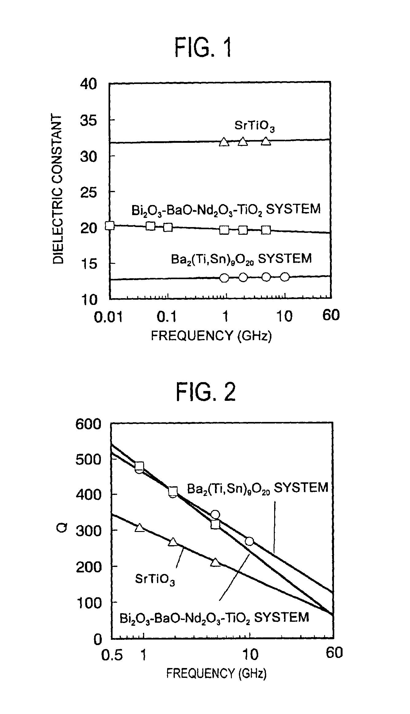
[0373]These samples were measured for dielectric constant at a frequency of 0.01 to 10 GHz, with the results being plotted in the graph of FIG. 1. The Q of the samples at a frequency of 1 to 10 GHz is shown in FIG. 2. These measurements were the same as in Example 1-1. A dielectric constant at a frequency of less than 100 MHz (0.1 GHz) was measured using an impedance / material analyzer 4291A by Hewlett Packard. The sample...

example 2-1

[0375]First, a ceramic powder and a polyvinylbenzyl ether compound were mixed in accordance with a formulation as shown in Table 5, thoroughly milled in toluene and dried at 90 to 120° C. for about 2 hours. This was ground into a powder of the ceramic powder and polyvinylbenzyl ether compound mixture, having a mean particle size of 50 to 1,000 μm. The mixture powder was placed in a mold of 6.5 cm×5 cm and cured at 120 to 200° C. for 2 hours, obtaining the end composition.

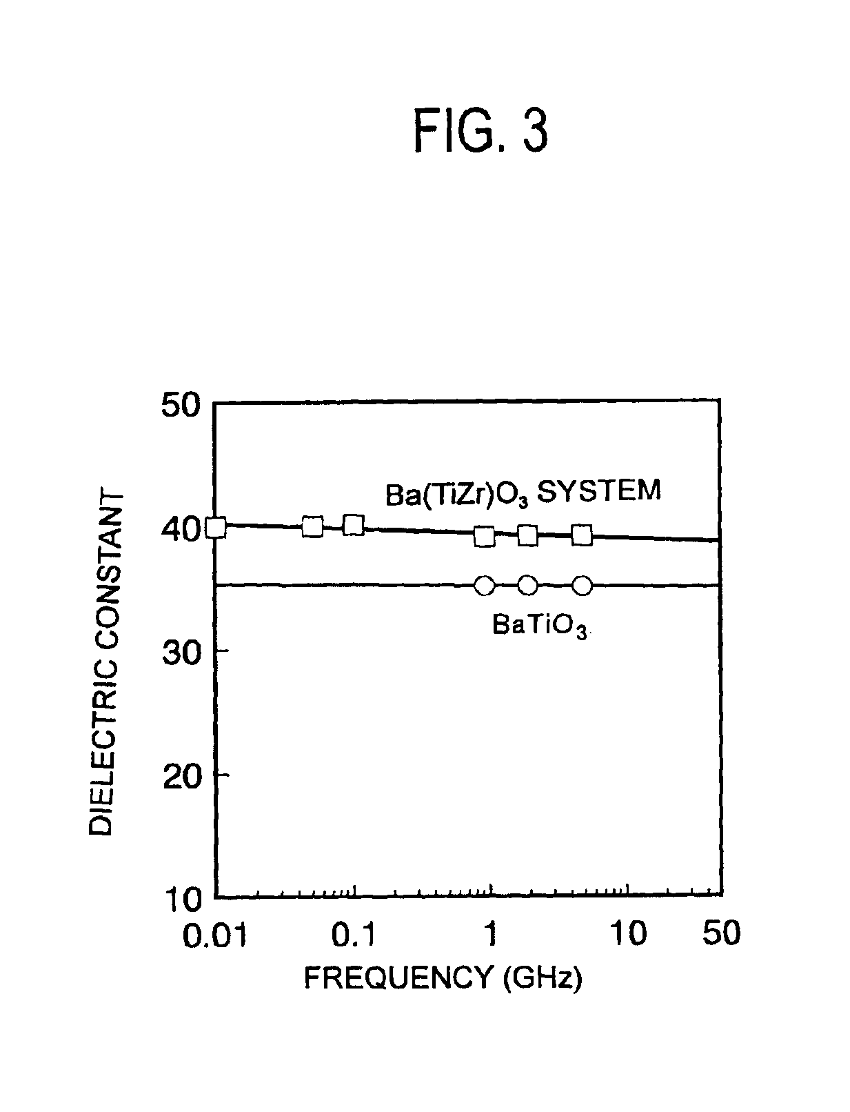
[0376]The ceramic powders used were BaTiO3 (mean particle size 0.5 μm) and Ba(Ti,Zr)O3 base (mean particle size 5 μm) powders.

[0377]The polyvinylbenzyl ether compound (VB) used was of the formula (1) wherein R1 is methyl, R2 is benzyl, R3 is a mixture of hydrogen and vinylbenzyl in a molar ratio of 0:100, and n=3.

[0378]From each of the compositions, a rod sample of about 1.0 mm square by about 6.5 mm long was formed and measured for dielectric constant at 2 GHz by the cavity resonator perturbation method using a tes...


PUM

PropertyMeasurementUnit
molar ratioaaaaaaaaaa
mean particle sizeaaaaaaaaaa

Abstract

A composite dielectric material comprising a resin resulting from a polyvinylbenzyl ether compound and a dielectric ceramic powder dispersed therein is useful in the high-frequency region. A composite magnetic material comprising a polyvinylbenzyl ether compound and a magnetic powder is also provided as well as a flame retardant material comprising a polyvinylbenzyl ether compound and a flame retardant. These materials may be used in the fabrication of substrates, prepreg sheets, coated metal foils, molded items, and metal foil-clad substrates.

Description

[0001]This invention relates to composite dielectric materials having a relatively high Q and a relatively high dielectric constant and suitable for use in electronic parts such as strip lines, impedance matching circuits, delay circuits and antennas.BACKGROUND OF THE INVENTION[0002]With the diversified advance of the electronic technology, there are diversified performance requirements of concern for insulating materials intended for use in electronic devices. In particular, printed wiring boards have been used in a very wide range of application, and the performance requirements on substrates thereof have been diversified. Under the circumstances, there are many different requirements regarding dielectric characteristics.[0003]Low-dielectric constant printed wiring boards have been developed with a focus placed on high speed propagation, high characteristic impedance, size reduction or cross-talk reduction. On the other hand, high-dielectric constant substrates are needed to meet ...

Claims


Application Information

Patent Timeline
Patent Type & Authority Patents(United States)
IPC IPC(8): H01B3/44H01P5/16H01Q1/38H01P1/203H01P7/08H01P5/18H01P7/04H01P1/20H01P1/205H01P5/10H05K9/00H05K1/03H05K1/16H05K1/02
CPCH01B3/442H01P1/20345H01P1/2056H01P5/10H01P5/185H01P5/187H01P7/04H01P7/082H01P7/084H01Q1/38H05K1/0373H05K9/0039H01P1/203H05K2201/086H05K1/024H05K1/0326H05K1/162H05K1/165H05K2201/012H05K2201/0209H05K9/0075Y10T428/31692Y10T428/31855C08K3/00
Inventor TAKAYA, MINORUKOBUKE, HISASHIENDO, TOSHIKAZUTAKAHARA, SEIJIABE, TOSHIYUKIOHKAWA, HIROSHIGESASAKI, MASAMIKAWABATA, KENICHI
Owner TDK CORPARATION
Why Eureka
Eureka Blog
Learn More