
Cellular panel and method and apparatus for making the same

a technology of zig-zag-shaped sheets and panels, which is applied in the field of cell-type insulation panels, can solve the problems of less attractive panels for some purchasers, less efficient method for fabricating panels made from zig-zag-shaped sheets, and increased difficulty in controlling

Inactive Publication Date: 2005-06-21
NEWELL OPERATING COMPANY
View PDF196 Cites 11 Cited by
  • Summary
  • Abstract
  • Description
  • Claims
  • Application Information

AI Technical Summary

Benefits of technology

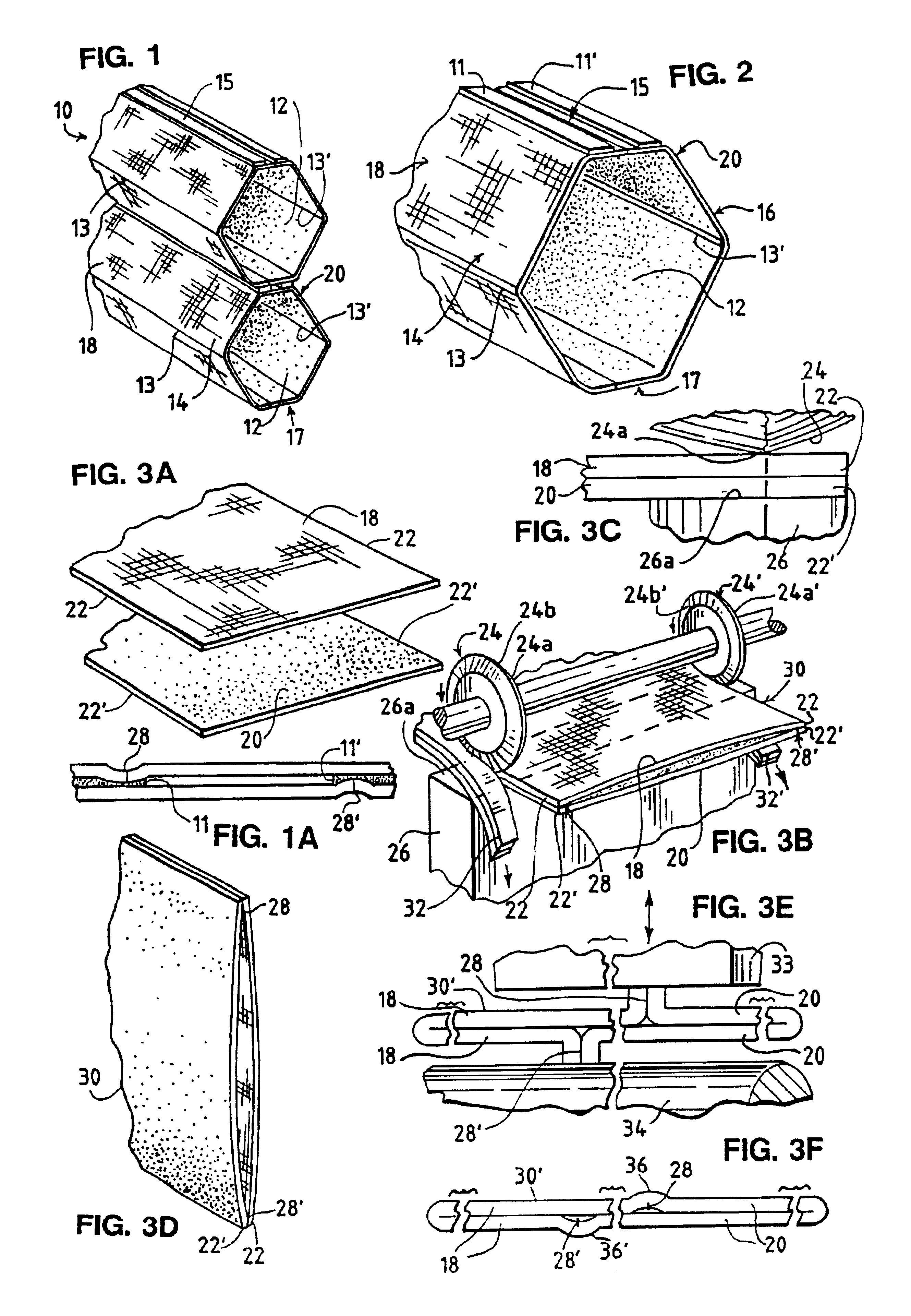
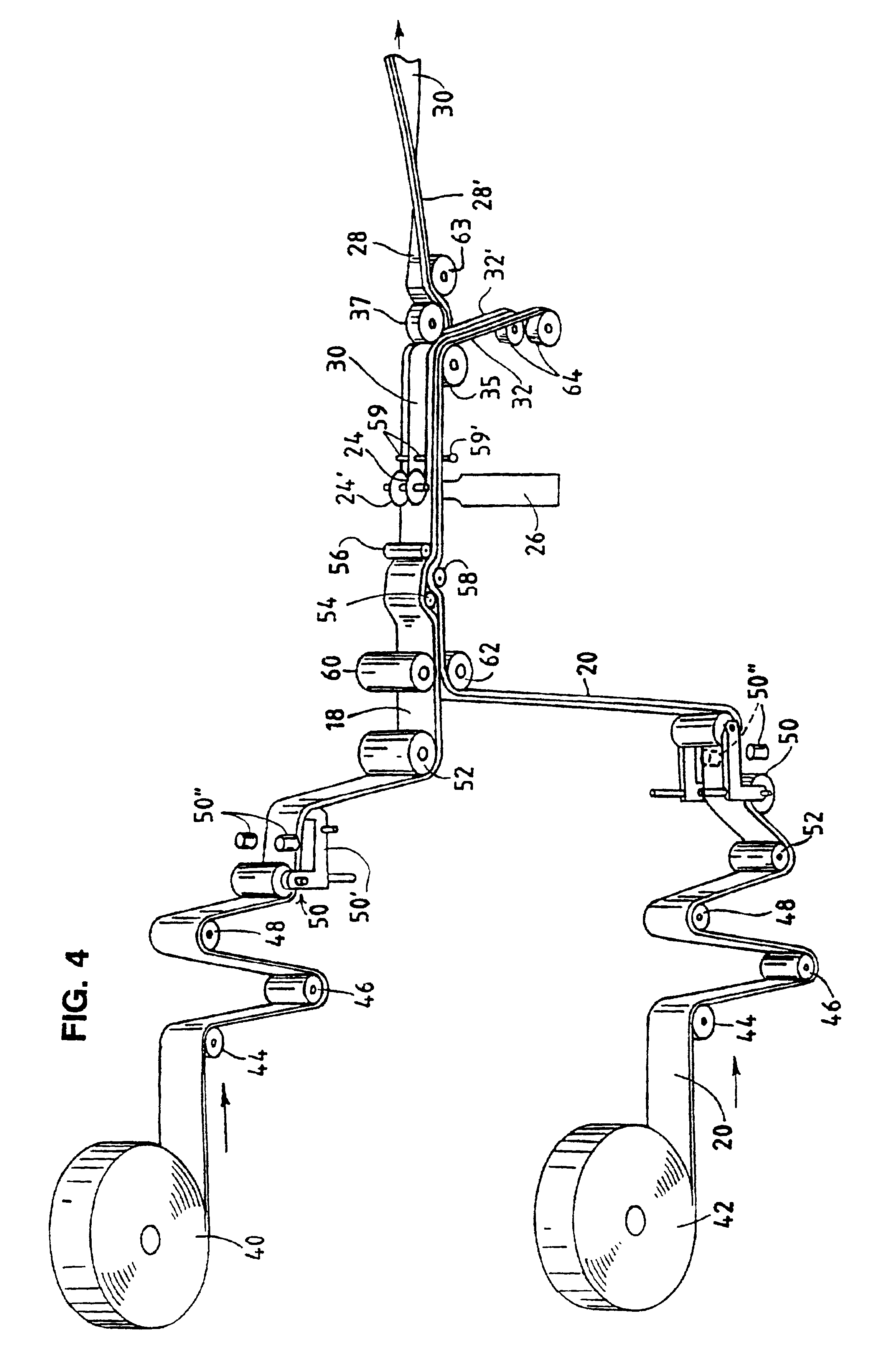
[0010]It is preferred in all forms of the invention that the cellular panel be made by a method and with apparatus that initially is either a continuous tubular or flat web formed from two or more narrow, continuous substrate sheets or webs of completely different material which form the front and the rear walls of the cellular panel to be made therefrom. The continuous substrate sheets, when made of a thermoplastic material, are secured together, preferably by sonically welding their abutting longitudinal margins. This permits efficient mass production of panels of various constructions by cutting strips from the web and laminating the strips together in the various ways to be described.
[0013]This web-reforming apparatus reflattens the tubular web in a plane preferably less than 90° from the original plane of the flat tubular web. This brings the welded margins of the flat tubular web from the outer edges of the flat web to laterally offset positions on the flat top and bottom faces of the web. As longitudinally-spaced segments of this flattened web become the separate tubular sections of the completed panel, the welded portions of these tubular sections are located along the confronting faces thereof, which are not visible at the front or rear side of the completed panel. The two different appearing substrate sheets are then only visible respectively on the opposite sides of the panel. While in accordance with a broad aspect of the invention, the welded portions need not be laterally offset, it is desirable because the offset reduces the thickness of the panel when it is raised into a collapsed condition at the top of a window. In all applications of the present invention where the substrate sheets are sonically welded along their superimposed abutting margins, it is desirable to flatten the welded portions of the substrate sheets. This process assures only a slight bulging of the substrate material therein, further reducing the thickness of the panel when in its collapsed configuration.
[0016]When forming a light-controlling panel, the initial continuous web is constructed preferably of three, differently-appearing substrate sheets welded together at their confronting longitudinal margins. The central substrate sheet is made from an opaque material. The other two substrate sheets positioned on opposite sides of the opaque central substrate sheet, are made from a narrower sheet of sheer material preferably of different mesh size or mesh shape, to eliminate a Moire effect. The three-substrate web is preferably made by positioning one of the narrower sheer substrate sheets over and along one of the side margins of the wider opaque substrate sheet and positioning the other narrower sheer substrate sheet beneath the wider opaque web along the opposite side margin thereof. These substrate sheets so positioned are moved past a pair of sonic welders positioned along the opposite longitudinal margins of the substrate sheets, where each welder welds only the two layers of sheet material located thereat. The resulting three-substrate web is then unfolded so that the completed panel can be made by one of two methods.
[0020]Another method for fabricating a light-controlling cellular panel eliminates the folding of the initially flat three-substrate webs. Before the flat web is cut into strips, spaced bands of adhesive are applied to the top surface of the web in a pattern which effects a special strip laminating pattern. The adhesive-coated flat web is then transversely cut into flat strips of equal length. The strips are laminated together by sequentially laterally shifting the strips from their original aligned longitudinally spaced positions. Each laterally shifted strip is next laminated so that the outer longitudinal margin of one of the outermost light-passing substrate sheets of each strip is adhered to the strip cut before it at the innermost longitudinal margin of the corresponding light-passing substrate sheet thereof, and the inner longitudinal margin of the other outermost light-passing substrate sheet of the former strip is adhered to the latter previously cut strip at the outer longitudinal margin of the corresponding outer substrate sheet. The resulting panel formed from the laterally-shifted laminated strips, when expanded, places the light-passing substrate sheets in positions where one of the light-passing substrate sheets of each strip forms a vertical front wall of an expanded tubular section of the panel, the other light-passing substrate sheet of the same strip forms a vertical rear wall of the adjacent expanded tubular section of the panel, and the opaque substrate sheet of that strip forms the horizontal top or bottom wall in common between adjacent cells of the panel.

Problems solved by technology

If the sheet forming each tubular strip is made of an expensive material to give the front side of the panel an attractive appearance, the high cost of the portion of the same sheet which is to face the window is an undesired expense.
However, this type of panel is less attractive to some purchasers than the panel having pointed oval, hexagonal or rectangular cells.
Also, the method required for fabricating the panel made from zig-zag shaped sheets is less efficient and more difficult to control than the method used to make a panel of separate folded strips of material adhesively secured together.
Most of the methods previously used to fabricate this type of light-controlling panel did not permit the ready manufacture of any desired width of the panel.

Method used


Image

  • Cellular panel and method and apparatus for making the same
  • Cellular panel and method and apparatus for making the same
  • Cellular panel and method and apparatus for making the same

Examples


Embodiment Construction

The Embodiment of FIGS. 1-5

[0055]While this invention is susceptible of many different forms, there is shown in the drawings and will herein be described in detail various preferred embodiments of the invention, with the understanding that the present disclosure is to be considered as an exemplification of the broad principles of the invention and is not intended to limit the broad aspects of the invention to the embodiments illustrated. The various different details of the various embodiments of the invention are, in some cases, due to their different applications and, in other cases, due to progressive improvements to earlier developed embodiments.

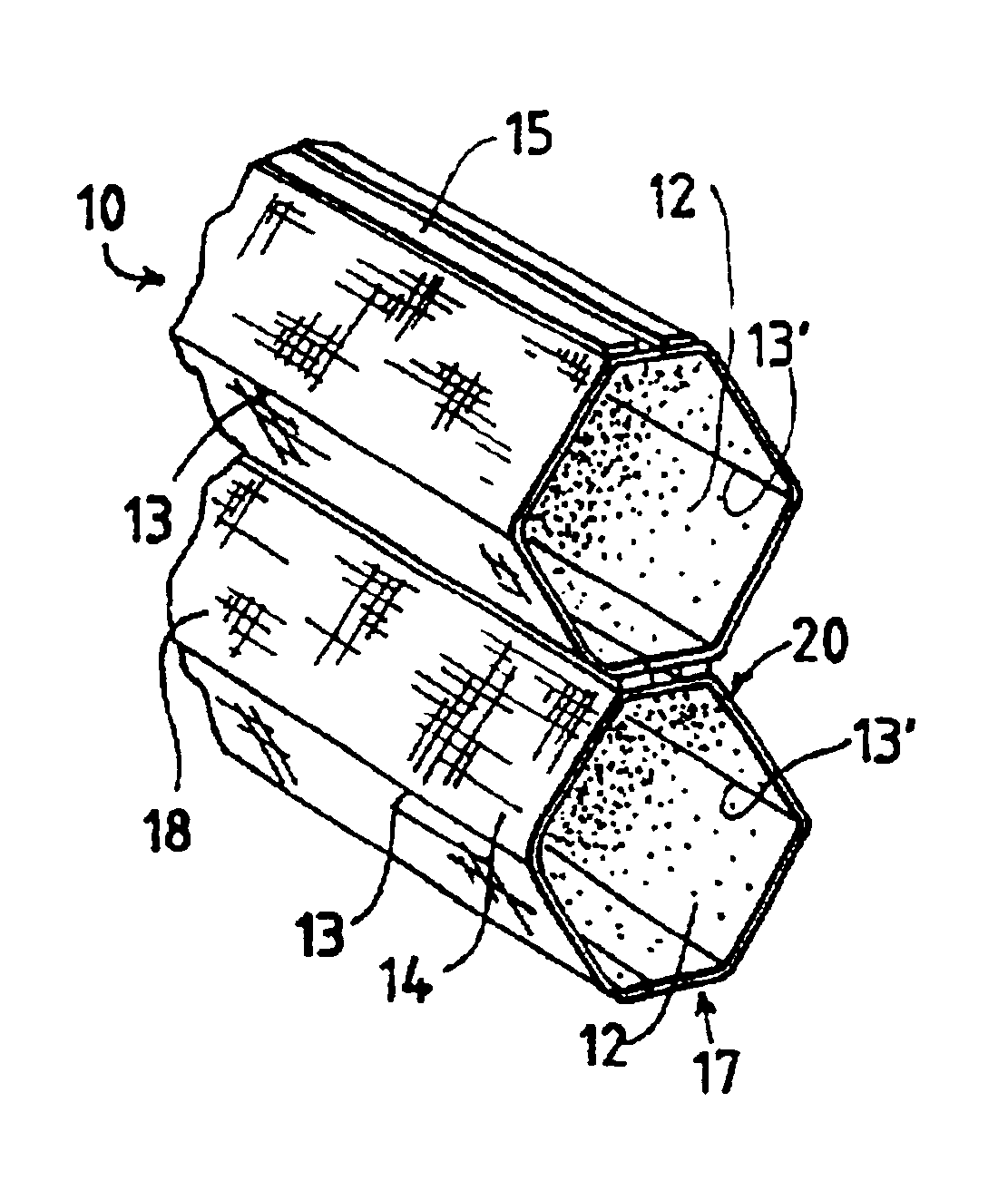
[0056]Referring now to the drawings, FIG. 1 shows a portion of a non-light controlling closed tube cellular panel 10 in its expanded state, formed from laminated horizontally elongated vertically aligned tubular sections or cells 12. This is the most preferred panel embodiment of the present invention where the panel is not light-control...


PUM

PropertyMeasurementUnit
Angleaaaaaaaaaa
Thicknessaaaaaaaaaa
Pressureaaaaaaaaaa

Abstract

An expandable and contractible cellular panel 10 comprises a plurality of parallel, aligned, elongated tubular sections 12 secured together at the median region of their adjacent longitudinal margins to form the panel 10. The adjacent tubular sections 12 of the panel 10 are made of a pair of substantially identical separate strips of sheet material from those forming the other adjacent tubular sections 12. The various adjacent pairs of strips are laminated together along their confronting longitudinal margins. Each strip is made of at least two separate flexible substrate sheets 18,20 having completely different appearances, and are secured together by welding together their longitudinal margins. The corresponding substrate sheets 18,20 of all the strips have corresponding positions in the panel 10, so that all the substrate sheets having one appearance are on one side of the panel 10 and those having a different appearance are on the other side of the panel 10, and the welded portions 28,28′ are located in the laminated portion of the strips where they are hidden from view.

Description

CROSS-REFERENCE TO RELATED APPLICATIONS[0001]This is a division of application Ser. No. 09 / 442,090 titled “CELLULAR PANEL AND METHOD AND APPARATUS FOR MAKING THE SAME” filed Nov. 11, 1999, now U.S. Pat. No. 6,284,347; which is a continuation of U.S. patent application Ser. No. 08 / 880,569 filed Jun. 23, 1997, now U.S. Pat. No. 6,045,890; which is a continuation of U.S. patent application Ser. No. 08 / 273,469 filed Jul. 11, 1994 now U.S. Pat. No. 5,888,639; which is a continuation of U.S. patent application Ser. No. 08 / 273,469 filed Jul. 11, 1994, abandoned, all of which are incorporated by reference herein.BACKGROUND OF THE INVENTION[0002]The present invention relates to cellular insulation panels. It has one of its most important applications as an insulating panel for covering windows or other openings. These panels most commonly comprise a plurality of tubular sections adhesively secured together. The panel can be oriented so that the tubular sections form a horizontally contractib...

Claims


Application Information

Patent Timeline
IPC IPC(8): E06B9/262E06B9/26E06B9/266B32B3/12B32B7/02
CPCB29C65/7443B29C65/749B29C66/03241B29C66/03242B29C66/1122B29C66/437B29C66/5227B29C66/63B29C66/939B29C67/0014E06B9/262E06B9/266B29C65/7847B29C66/432B29C65/48B29C66/93451B29C65/00B29C66/50B29C53/385Y10T428/24165B29C65/52B29C65/7894B29C2793/00B29L2031/601E06B2009/2627B29C65/08Y10T156/1067Y10T428/24686Y10T156/1052Y10T428/24669Y10T428/24149B29C66/54Y10T428/24694Y10T156/1075Y10T428/2476Y10T156/1069Y10T428/24661Y10T156/1062Y10T156/13B29C66/73921B29C66/83411B29C65/086B29C66/836B29C66/73361B29C66/73365B29C66/71B29C66/8161B29C66/8223Y10T428/249953B29C66/133B29C66/137B29K2067/00
Inventor GREEN, JACE N.RUGGLES, BRYAN K.CHACON, RICHARD F.
Owner NEWELL OPERATING COMPANY
Learn More