Antilock brake control system for vehicle

a technology of antilock brakes and control systems, applied in the direction of braking systems, vehicle components, brake components, etc., can solve the problems of slow change of electric current, inability to respond, and inability to respond, so as to suppress the generation of imbalances and reduce the rate of electric curren

Inactive Publication Date: 2005-06-21
HONDA MOTOR CO LTD
View PDF8 Cites 19 Cited by
  • Summary
  • Abstract
  • Description
  • Claims
  • Application Information

AI Technical Summary

Benefits of technology

[0019]With such arrangement of the fifth feature, the capacity of each of the diodes on the side of the left and right rear wheels is set at the relatively small value. Therefore, in the coils of the normally-opened solenoid valves corresponding the left and right rear wheel brakes, an electric current decreasing rate is high as compared with the diode having a larger capacity, when the electric current flowing through the coils is slowly decreased by the diode upon stoppage of the supply of the electric current to the coils. Moreover, a difference between the capacities of the diodes individually corresponding to the left and right rear wheels also becomes small, so that it is possible to suppress the generation of an imbalance between the braking fluid pressures of the left and right rear wheel brakes.

Problems solved by technology

However, when the control mode is changed from a turned-on state to a middle current value state, the change in electric current is slow, so that the response is retarded.
However, the response is inevitably retarded, because the turned-off state exists in the middle.
However, if the select-low controls are carried out simultaneously for the left and right rear wheels, an imbalance may be generated in some case between braking pressures of the left and right rear wheel brakes due to a difference between the capacities of diodes individually corresponding to the left and right rear wheels and a difference between inductances of coils individually corresponding to the left and right rear wheels.
Moreover, there is a possibility that the imbalance is generated significantly by a reduction in responsiveness due to a larger capacity of the diode.

Method used


Image

  • Antilock brake control system for vehicle
  • Antilock brake control system for vehicle
  • Antilock brake control system for vehicle

Examples


first embodiment

[0040]the present invention will now be described with reference to FIGS. 1 to 8.

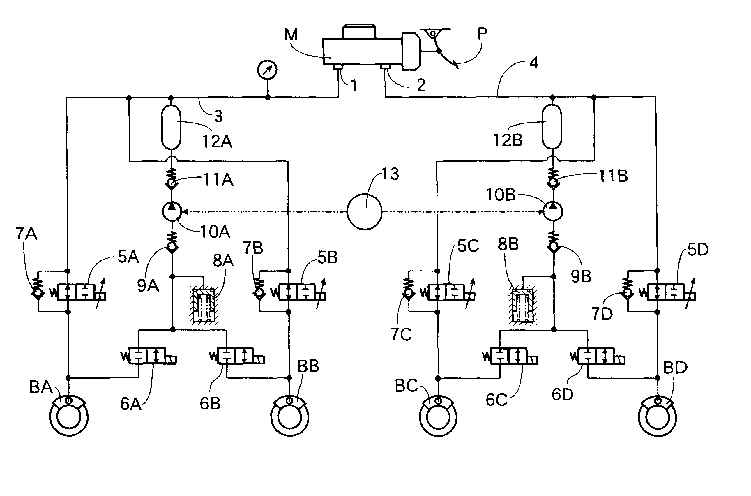
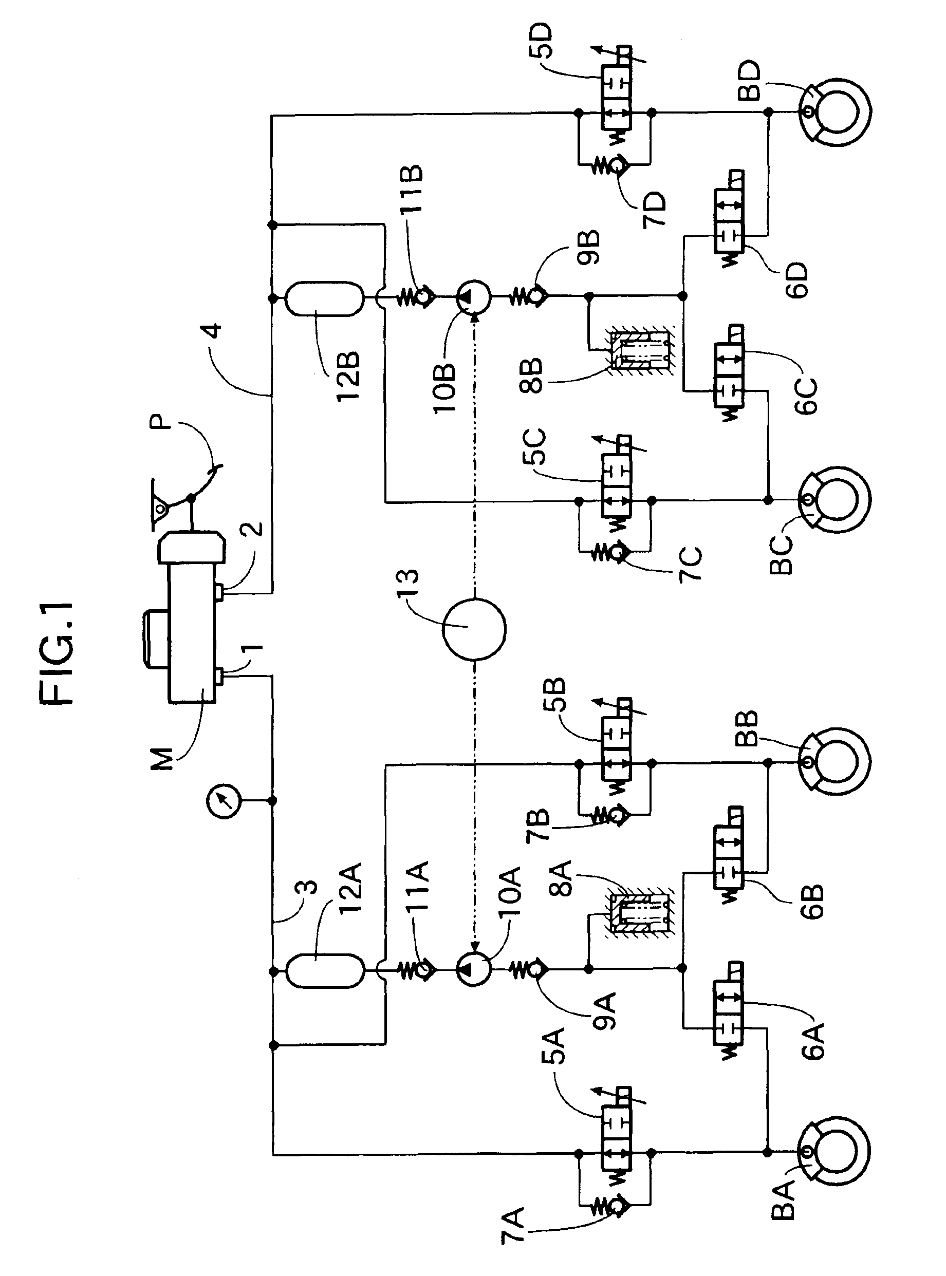
[0041]Referring first to FIG. 1, a tandem-type master cylinder M as a braking fluid pressure generating means includes first and second output ports 1 and 2 adapted to generate a braking fluid pressure corresponding to a depressing force applied to a brake pedal by a vehicle driver. First and second output fluid pressure passages 3 and 4 are connected to the first and second output ports 1 and 2, respectively.

[0042]Normally-opened solenoid valves 5A and 5B are interposed between the first output fluid pressure passage 3 and a left front wheel brake BA and a right rear wheel brake BB mounted on a left front wheel and a right rear wheel respectively to individually correspond to the left front wheel brake BA and the right rear wheel brake BB. Normally-opened solenoid valves 5C and 5D are interposed between the second output fluid pressure passage 4 and a right front wheel brake BC and a left rear wheel br...


PUM


Abstract

An antilock brake control system for a vehicle including normally-opened solenoid valves, normally-closed solenoid valves, and diodes. Each of the normally-opened solenoid valves is switched over among a turned-on state in which a predetermined first electric current is permitted to flow through the coil, a turned-off state in which the supply of the electric current to the coil is topped, and a middle state in which a second electric current lower than the first electric current is permitted to flow. In addition, the system includes a switch that is maintained in an electrically disconnecting state during shifting of each of the normally-opened solenoid valves from the turned-on state to the middle state, until the shifting is completed.

Description

BACKGROUND OF THE INVENTION[0001]1. Field of the Invention[0002]The present invention relates to an antilock brake control system for a vehicle, including normally-opened solenoid valves and normally-closed solenoid valves corresponding wheel brakes, and a diode capable of exhibiting a function of slowly decreasing electric current supplied to a coil of each of the normally-opened solenoid valves when the supply of the electric current to the coil has been cut off.[0003]2. Description of the Related Art[0004]There is an antilock brake control system for a vehicle already known, for example, from Published Japanese Translation No. 10-504259 of PCT Application No. PCT / DE / 00588 and the like, in which a diode is connected in parallel to a coil of each of normally-opened solenoid valves in order to the suppress the generation of a noise upon closing / seating of each of the normally-opened solenoid valves.[0005]The diode is adapted to slowly decrease the electric current flowing through th...

Claims


Application Information

Patent Timeline
Patent Type & Authority Patents(United States)
IPC IPC(8): B60T8/42B60T8/36
CPCB60T8/36B60T8/4275B60T8/367B60T8/363
Inventor INAGAKI, HIROMIGOTOH, MASARUKOBORI, HIDETOSHI
Owner HONDA MOTOR CO LTD
Why Eureka
Try Eureka