
Disc having grooves and pits with different depths, and method for manufacturing the disc

a technology of optical discs and pits, which is applied in the field of optical discs with grooves and pits with different depths, can solve the problems of unreliable pit signal level of the same pit and groove depth, high manufacturing cost, and complicated process with low yield. achieve the effect of improving the reproduction signal level of the pits

Inactive Publication Date: 2005-06-14
SAMSUNG ELECTRONICS CO LTD
View PDF22 Cites 17 Cited by
  • Summary
  • Abstract
  • Description
  • Claims
  • Application Information

AI Technical Summary

Benefits of technology

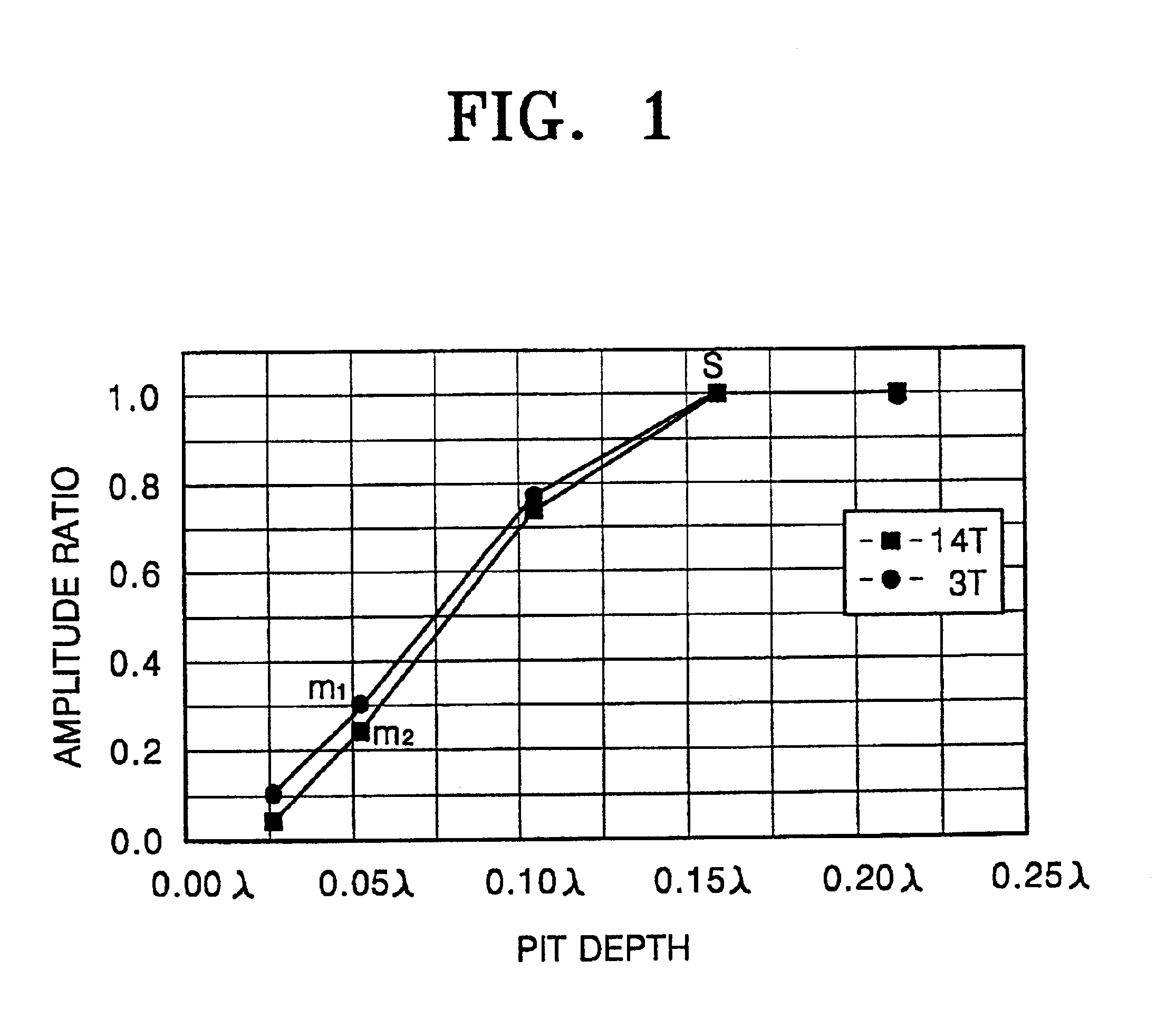
[0013]To solve the above problems, it is an object of the present invention to provide a new disc using only grooves as recording / reproduction regions and also having a reliable or an optimum signal level from both a pit region, such as a reproduction-only pit region (hereinafter referred to as pits) and the groove regions. In particular, it is an object of the present invention to provide a new disk having grooves and pits of different depths, for example, pits deeper than grooves, thereby improving reproduction signal level of the pits.
[0014]Therefore, the present invention can provide, for example, a DVD-RW disc having a reliable or an optimum signal level from both reproduction-only pit regions and groove regions.

Problems solved by technology

Such a pit signal level from the same pit and groove depth is unreliable.
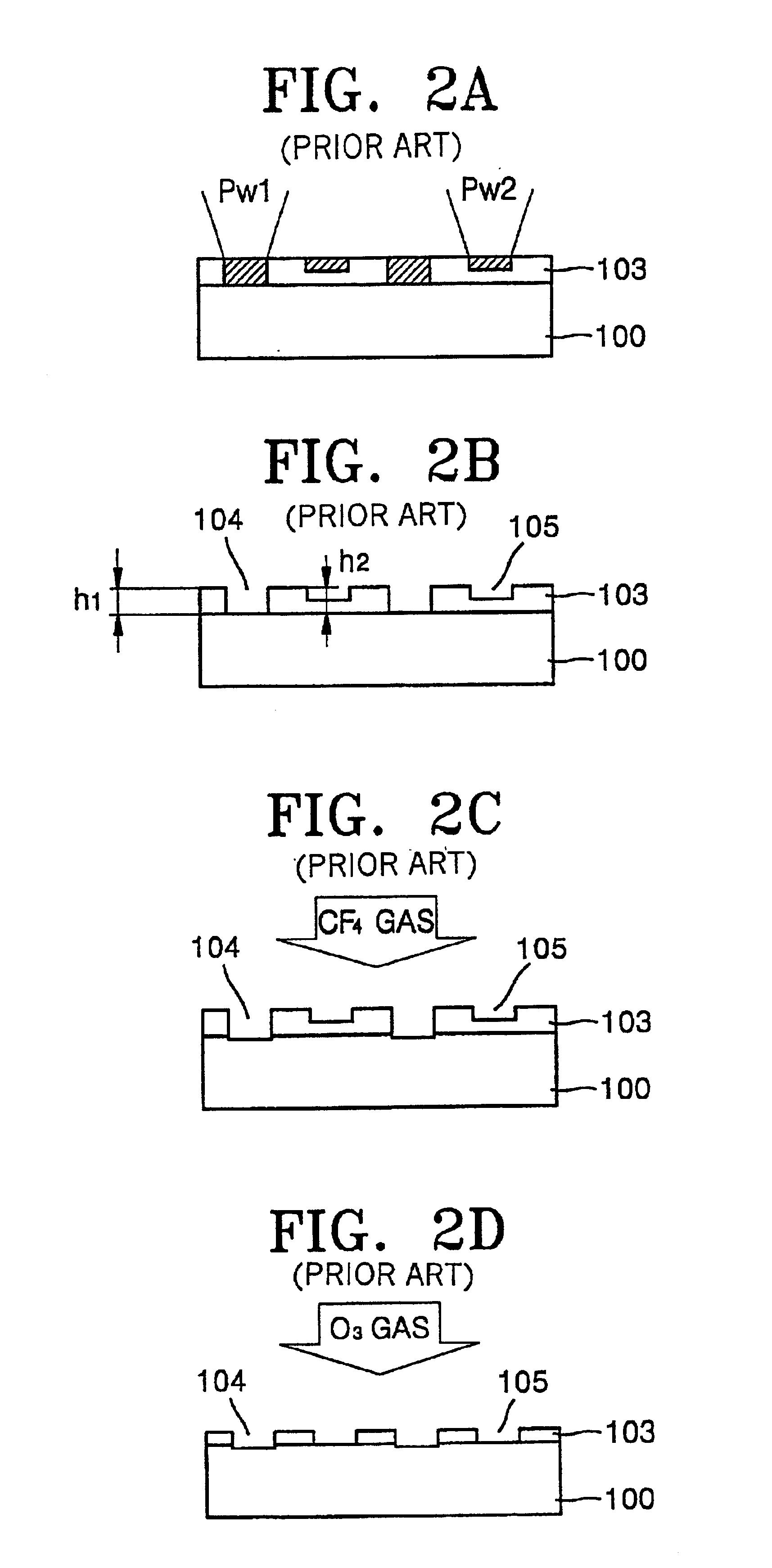
According to the conventional disc manufacturing process, the etching is performed twice, so that the entire process is complicated with low yield.
In addition, the manufacturing cost is high.

Method used


Image

  • Disc having grooves and pits with different depths, and method for manufacturing the disc
  • Disc having grooves and pits with different depths, and method for manufacturing the disc
  • Disc having grooves and pits with different depths, and method for manufacturing the disc

Examples


Embodiment Construction

[0028]Reference will now be made in detail to the present preferred embodiments of the present invention, examples of which are illustrated in the accompanying drawings, wherein like reference numerals refer to the like elements throughout. The embodiments are described below in order to explain the present invention by referring to the figures.

[0029]An embodiment of a DVD-RW disc having grooves and pits with different depths according to the present invention is shown in FIGS. 3 and 4. The disc 40 includes a groove 10 having record marks 11, a first land 14 with land pre-pits 16 for address signals, which are spaced a predetermined distance apart along the track direction of the disc 40, and reproduction-only pits (simply referred to as pits) 15. A region having the pit 15 is referred to as a second land 17.

[0030]It is preferable that the groove 10 and the pit 15 both lie on the same base line 12 and the groove 10 and the pit 15 have different depths d1 and d2, respectively. Altern...


PUM


Abstract

A disc having grooves and pits with different depths according toλ / 8n≦d3≦λ / 5nwhere d3 is a difference in depths between the grooves and the pits, λ is the wavelength of a light source, and n is the refractive index of the disc. A disc having grooves and pits with different depths can be manufactured without etching by using at least two stampers. Manufacturing a master by depositing photoresist over a glass master, forming a first land region and a second land region having different depths by laser cutting with laser beams having different power levels. Stamping a father stamper having a groove region and a pit region from the master, the shape of the father stamper inverse of the master. Stamping a mother stamper from the father stamper, the shape of the mother stamper inverse of the father stamper. Manufacturing the disc with the mother stamper.

Description

CROSS REFERENCE TO RELATED APPLICATIONS[0001]This Application claims the benefit of Korean Application No. 00-30034, filed Jun. 1, 2000 in the Korean Patent Office, the disclosure of which is incorporated herein by reference.BACKGROUND OF THE INVENTION[0002]1. Field of the Invention[0003]The present invention relates to an optical disc having grooves and pits with different depths, and an easy method of manufacturing a disc having grooves and pits with different depths using a stamper obtained by stamping from a master an even number of times.[0004]2. Description of the Related Art[0005]Rewritable, erasable and reproducible optical discs, such as digital versatile disc random access memory (DVD-RAM) and DVD-rewritable (RW), include grooves for recording and / or reproduction. The main difference between DVD-RAM and DVD-RW is in their recording regions. In particular, information can be written to both land and groove regions of a DVD-RAM, and the DVD-RAM has separated addresses formed...

Claims


Application Information

Patent Timeline
IPC IPC(8): G11B7/013G11B7/26G11B7/007G11B7/0045G11B7/24035G11B7/2405G11B7/24079G11B7/24085G11B7/24091
CPCG11B7/007G11B7/263G11B7/261G11B7/24085G11B7/26
Inventor LEE, KYUNG-GEUNYOON, DU-SEOPPARK, CHANG-MINPARK, IN-SIK
Owner SAMSUNG ELECTRONICS CO LTD
Learn More