
Film-processing method and film-processing apparatus

a film processing method and film processing technology, applied in the field of film processing methods and film processing apparatuses, can solve the problems of difficult to achieve the most suitable process time, and the amount of electron irradiated onto the object to be processed may be either too much or too little, so as to achieve suitable film quality

Inactive Publication Date: 2005-06-07
TOKYO ELECTRON LTD
View PDF4 Cites 6 Cited by
  • Summary
  • Abstract
  • Description
  • Claims
  • Application Information

AI Technical Summary

Benefits of technology

[0007]According to the present invention, by detecting an end point of the process to the film based on an amount of electron during the process, a suitable irradiation of the electron beams onto the film on a surface of the object to be processed can be realized. Thus, a suitable film quality can be obtained.
[0012]According to the present invention, by detecting an end point of the process to the film based on an amount of electron during the process, a suitable irradiation of the electron beams onto the film on a surface of the object to be processed can be realized. Thus, a suitable film quality can be obtained.

Problems solved by technology

However, many of the SOD films are made of an organic material, and some of the SOD films are inferior in mechanical strength.
In modifying a film quality by using a conventional electron beam processing apparatus, even when processing conditions such as a process time of the electron beam processing apparatus are set based on a previous evaluation, it is difficult to achieve the most suitable process time because of an uniform amount of irradiation of electron beams onto an object to be processed.
That is, even with the same process time, the amount of electron irradiated onto an object to be processed may be either too much or too little.
Thus, it is difficult for a film on a surface of the object to be processed to obtain a desired film quality, which results in a reduction of throughput.
For example, if a process time for the EB cure is insufficient, curing is not completed and a desired film strength cannot be achieved.
Thus, a suitable film quality cannot be obtained.
On the other hand, an excess processing time for the EB cure degrades the k value, and thus a suitable film quality cannot be obtained.

Method used


Image

  • Film-processing method and film-processing apparatus
  • Film-processing method and film-processing apparatus
  • Film-processing method and film-processing apparatus

Examples


Embodiment Construction

[0033]The present invention is described below with reference to embodiments thereof shown in the accompanied drawings.

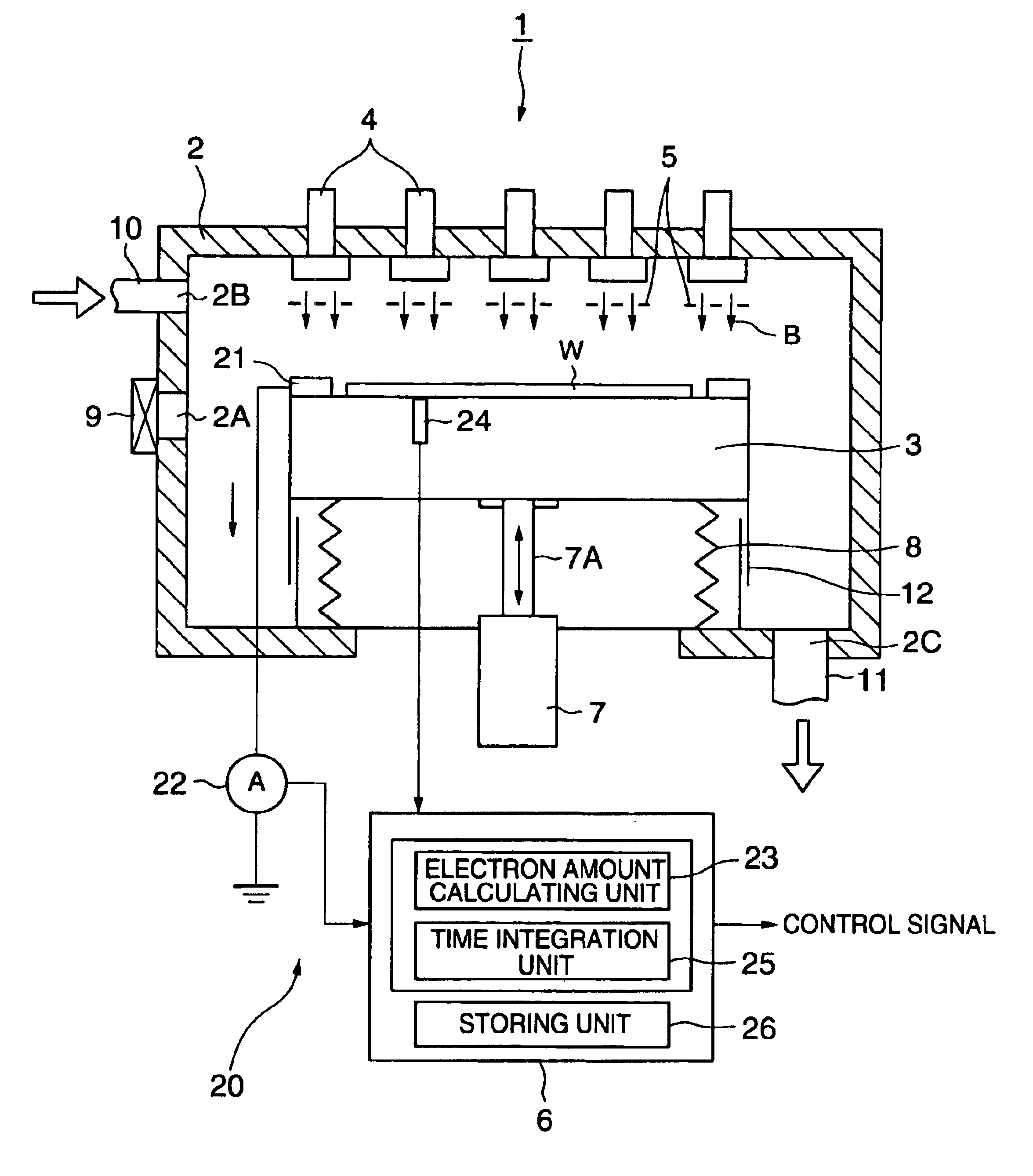
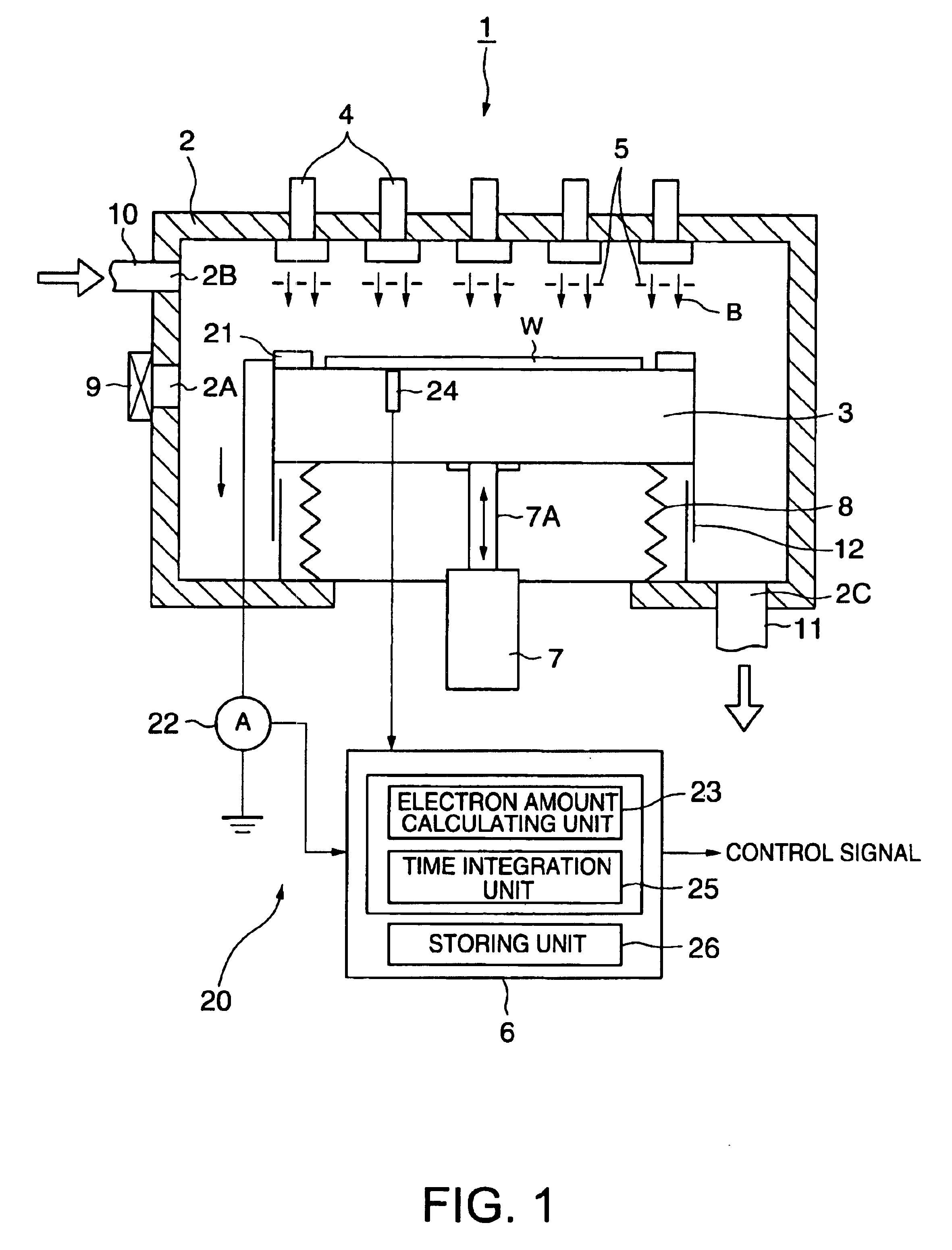
[0034]Referring FIG. 1, an embodiment of the film-processing apparatus according to the present invention is described.

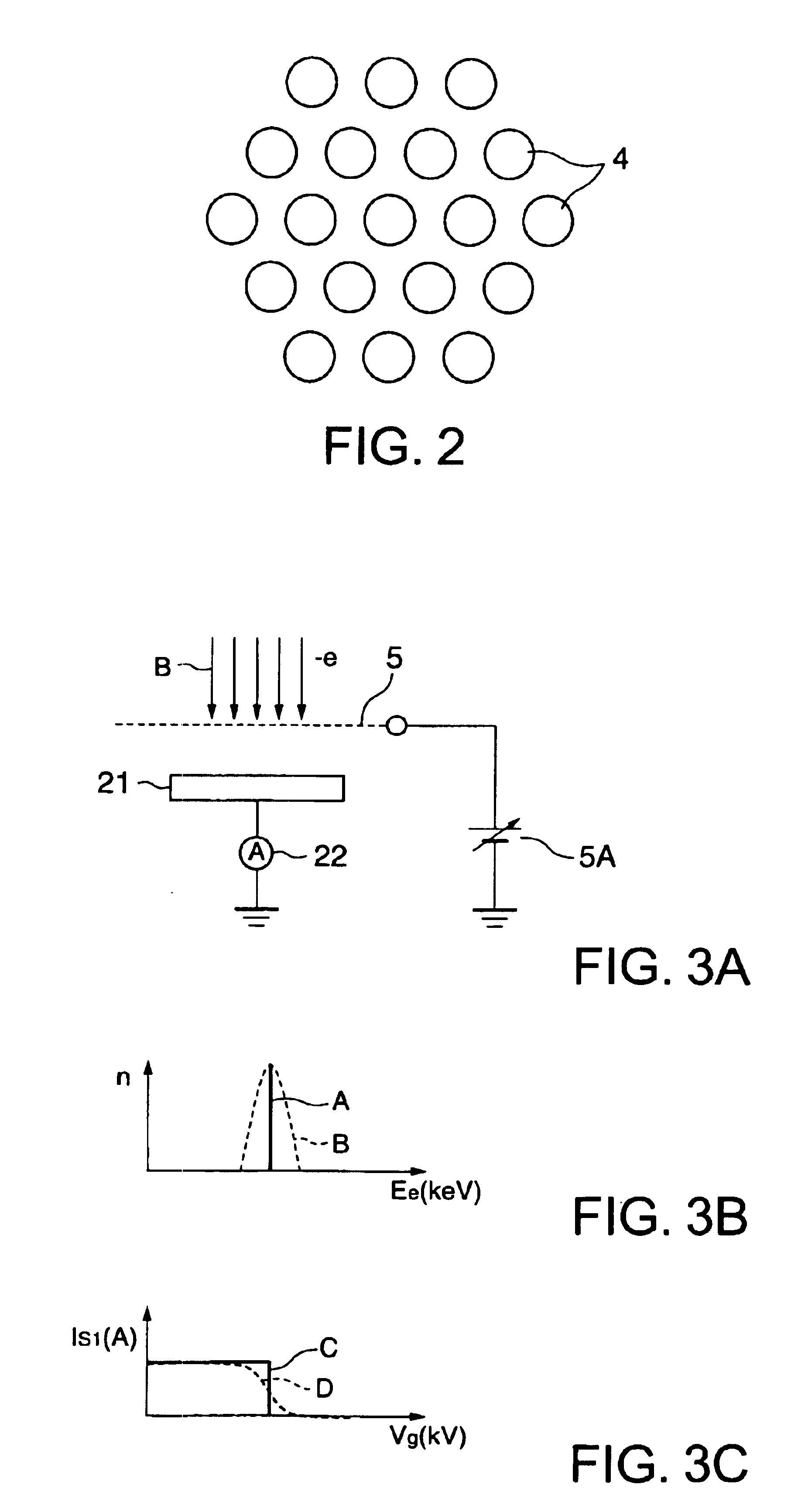
[0035]As shown in FIGS. 1 and 2, a film-processing apparatus 1 of the embodiment, for example, includes a decompressible processing container 2 made of aluminum or the like; a stage 3 on which an object to be processed (wafer) W is mounted, the stage 3 being disposed on a center of a bottom surface of the processing container 2; a plurality of (e.g., 19) electron beam tubes 4 which are concentrically arranged on an upper surface of the processing container 2 opposed to the stage 3; and a grid electrode 5 which controls an amount of irradiation of electron beams B from the electron beam tubes 4. Under a control by a controller 6, the electron beams B are irradiated from the respective electron beam tubes 4 onto the whole surface of the wafer W mounte...


PUM


Abstract

A film-processing method according to the present invention includes: a processing step of irradiating electron beams onto a film on a surface of an object to be processed to conduct a process to the film; an electric-current measuring step of capturing the electron beams in a vicinity of the object to be processed to measure an electric-current value during the processing step; and a detecting step of detecting an end point of the process to the film, based on an amount of electron obtained by means of a time integration of the electric-current value. According to the present invention, a suitable irradiation of the electron beams onto the film on a surface of the object to be processed can be realized. Thus, a suitable film quality can be obtained.

Description

FIELD OF THE INVENTION[0001]The present invention relates to a film-processing method and a film-processing apparatus. More particularly, it pertains to a film-processing method and a film-processing apparatus which are capable of optimally processing a film such as an insulation film between layers on a surface of an object to be processed, e.g., a wafer.BACKGROUND OF THE INVENTION[0002]In accordance with greater integration and increased speed of semiconductor devices, wiring patterns have been miniaturized, and the reduction of parasitic capacitance generated by an insulation film between wirings has become increasingly important. In order to reduce parasitic capacitance generated by an insulation film between wirings of a minute wiring pattern, various organic materials of low dielectric constant have been developed in recent years. These organic materials have been used to form an insulation film between layers and a protective film as a Low-k material. This Low-k film material...

Claims


Application Information

Patent Timeline
IPC IPC(8): G03B27/42G03D3/00H01L21/02H01L21/30H01L21/70H01L21/768H01L21/312G03C5/16H01J7/24H01J37/304H01L21/66
CPCH01J37/304H01J37/317H01L22/26H01J2237/30466H01J2237/3156H01J2237/2482H01L22/00
Inventor ONISHI, TADASHIHAMA, MANABU
Owner TOKYO ELECTRON LTD
Learn More