Fluid ejection device with staggered ink drop generators

a technology ejection device, which is applied in printing and other directions, can solve the problems of large decrease in print speed, and vaporization of thin layer of ink, and achieve high density of ink drop generator, high print resolution, and high printing resolution

Inactive Publication Date: 2005-06-07
HEWLETT PACKARD DEV CO LP
View PDF8 Cites 12 Cited by
  • Summary
  • Abstract
  • Description
  • Claims
  • Application Information

AI Technical Summary

Benefits of technology

[0012]To overcome the limitations in the prior art as described above, and to overcome other limitations that will become apparent upon reading and understanding the present specification, the present invention is embodied in a monochrome ink jet printhead capable of multiple modes of operation that includes a high density of ink drop generators to provide high-resolution one-pass printing. In particular, the present invention can perform one-pass printing at a paper axis print resolution of greater than double the resolution of a single row. The present invention addresses at least one of the problems associated with a high-density array of ink drop generators and nozzles and provides high-quality one-pass printing having a high print resolution. In addition, the present invention allows for printing in multiple print modes depending on the desired print speed, print resolution and print quality.
[0013]The present invention includes as one embodiment a fluid ejection device coupled to an ink supply and having multiple printing modes, including a sufficient number of ink drop generators fluidically coupled to the ink supply device and formed in the fluid ejection device and arranged along at least three axes that are substantially parallel and spaced apart from each other to provide printing resolution of at least 600 dots per inch with each printing mode. The plurality of ink drop generators is arranged along four axes that are substantially parallel and spaced transverse to each other and wherein the plurality of ink drop generators arranged along the four axes are staggered with respect to each of the axes to decrease an effective pitch of the fluid ejection device to approximately one-fourth that of a plurality of ink drop generators arranged along a single axis.

Problems solved by technology

This superheating causes an explosive vaporization of the thin layer of ink and an ink drop ejection through an associated nozzle of the printhead.
One major disadvantage, however, of two-pass printing is that the extra passes greatly decrease the speed of the printer.
Such a large decrease in print speed is undesirable for some printing operations, but acceptable in others.
However, it is quite difficult to manufacture ink drop generator and nozzle structures that allow the high linear density of nozzles required for high print resolution printing.
For instance, ink drop generators must be fine enough to allow for tight spacing, ink drop volume must decrease with the tighter spacing, and the subsequent lower drop volume may not be compatible with the desired print mode.

Method used


Image

  • Fluid ejection device with staggered ink drop generators
  • Fluid ejection device with staggered ink drop generators
  • Fluid ejection device with staggered ink drop generators

Examples


Embodiment Construction

[0026]In the following description of the invention, reference is made to the accompanying drawings, which form a part thereof, and in which is shown by way of illustration a specific example whereby the invention may be practiced. It is to be understood that other embodiments may be utilized and structural changes may be made without departing from the scope of the present invention.[0027]I. General Overview

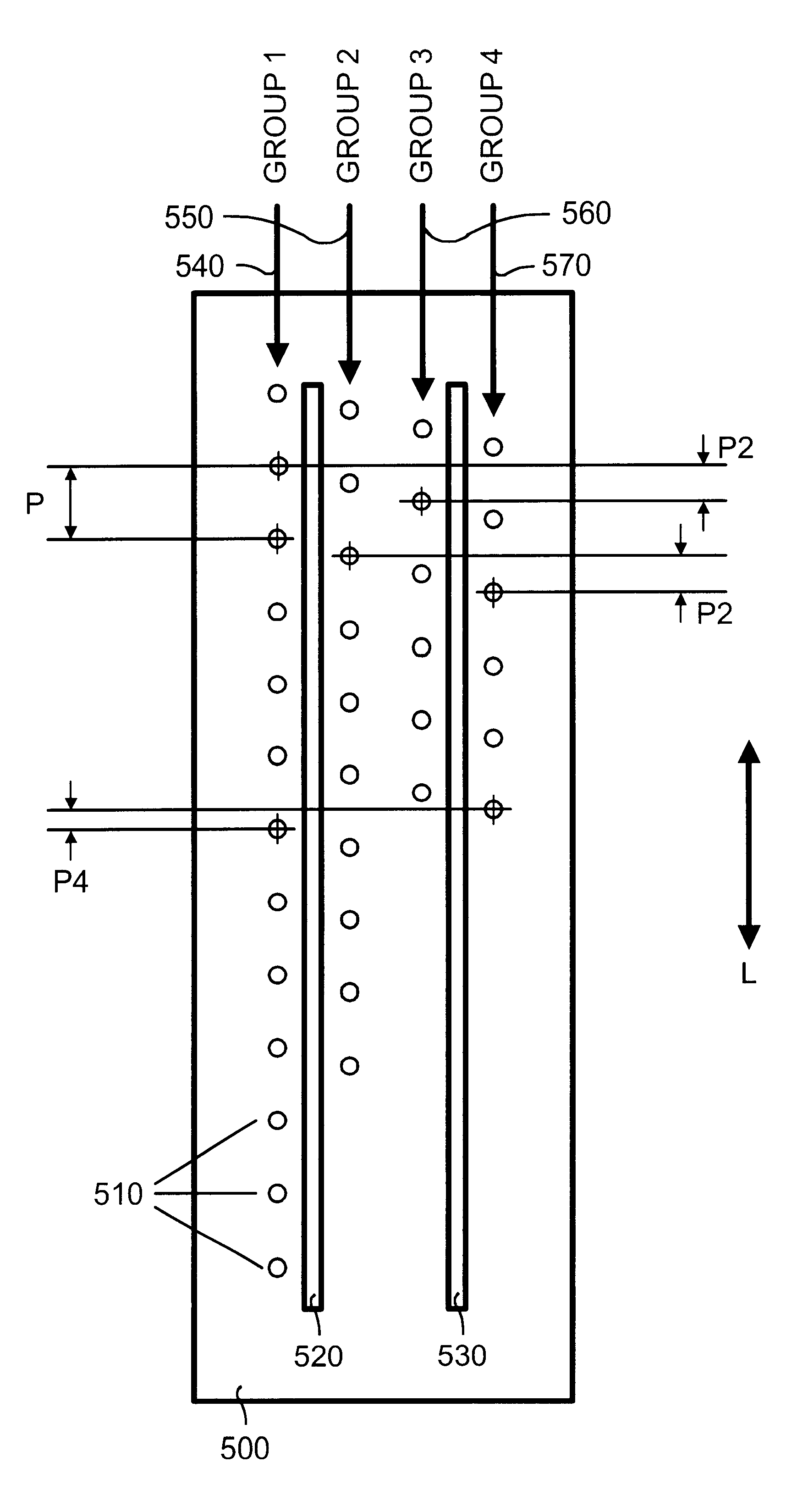
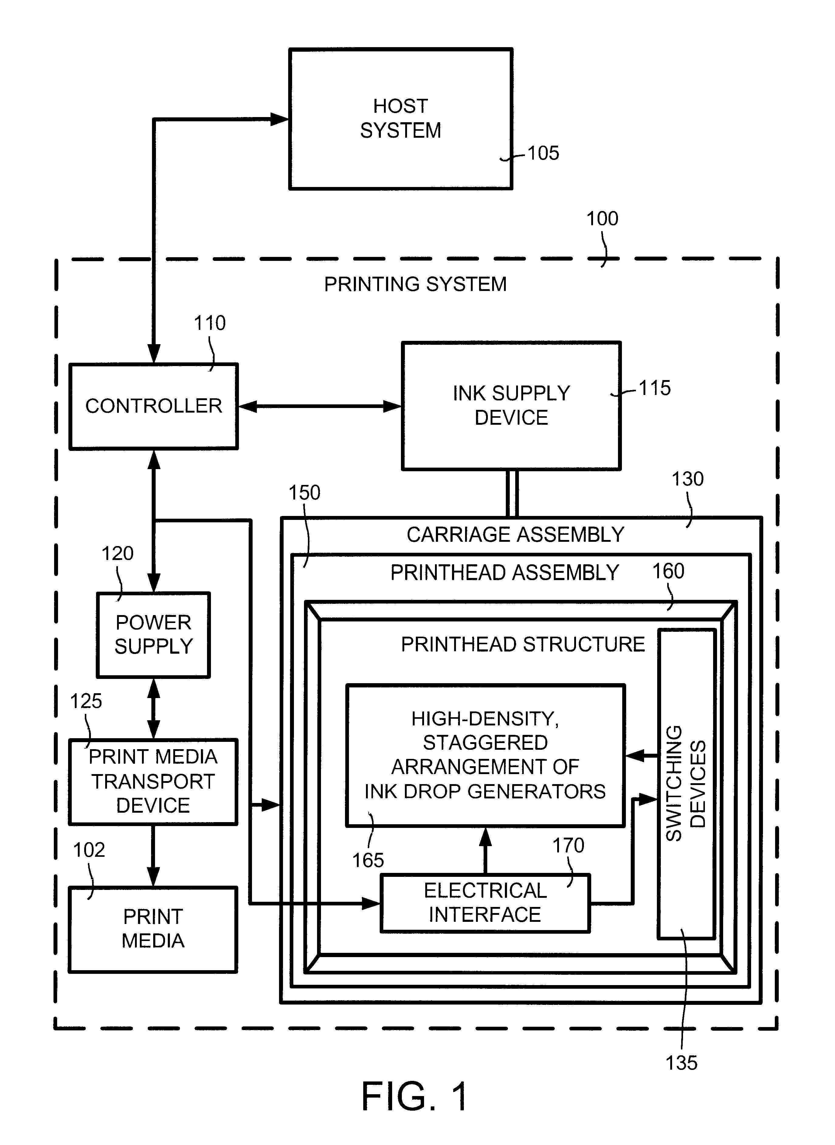
[0028]The present invention is embodied in a monochrome printhead having a high-density arrangement of interleaved or staggered ink drop generators. This arrangement provides the present invention with high-resolution and high-speed printing. The present invention has the ink drop generators arranged in at least three groups along at least three axes. An axis group contains a plurality of ink drop generators that are arranged along the corresponding axis (such as in a columnar group). Each axis has a centerline that is substantially parallel to a reference axis. An axis group is...


PUM


Abstract

The present invention includes as one embodiment a fluid ejection device coupled to an ink supply and having multiple printing modes, including a sufficient number of ink drop generators fluidically coupled to the ink supply device and formed in the fluid ejection device and arranged along at least three axes that are substantially parallel and spaced apart from each other to provided printing resolution of at least 600 dots per inch with each printing mode. The plurality of ink drop generators is arranged along four axes that are substantially parallel and spaced transverse to each other and wherein the plurality of ink drop generators arranged along the four axes are staggered with respect to each of the axes to decrease an effective pitch of the fluid ejection device to approximately one-fourth that of a plurality of ink drop generators arranged along a single axis.

Description

BACKGROUND OF THE INVENTION[0001]1. Field of the Invention[0002]The present invention relates to a fluid ejection device with staggered ink drop generators.[0003]2. Related Art[0004]Thermal ink jet (TIJ) printers are popular and widely used in the computer field. These printers are described by W. J. Lloyd and H. T. Taub in “Ink Jet Devices,” Chapter 13 of Output Hardcopy Devices (Ed. R. C. Durbeck and S. Sherr, San Diego: Academic Press, 1988) and U.S. Pat. Nos. 4,490,728 and 4,313,684. Ink jet printers produce high-quality print, are compact and portable, and print quickly and quietly because only ink strikes a print medium (such as paper).[0005]An ink jet printer produces a printed image by printing a pattern of individual dots (or pixels) at specific defined locations of an array. These dot locations, which are conveniently visualized as being small dots in a rectilinear array, are defined by the pattern being printed. The printing operation, therefore, can be pictured as the fi...

Claims


Application Information

Patent Timeline
Patent Type & Authority Patents(United States)
IPC IPC(8): B41J2/15B41J2/145B41J2/04B41J2/01B41J2/05
CPCB41J2/15B41J2/04
Inventor TORGERSON, JOSEPH M.BAKKOM, ANGELA W.MACKENZIE, MARK H.
Owner HEWLETT PACKARD DEV CO LP
Why Eureka
Try Eureka