
Method and a plate for digitally-imaged offset printing

a technology of offset printing and offset plate, applied in thermography, instruments, photosensitive materials, etc., can solve the problems of difficult modulation, high cost of uv laser, unstable film processing, etc., and achieve the effect of simple manner, inexpensive and simpl

Inactive Publication Date: 2005-05-31
KODAK IL
View PDF22 Cites 52 Cited by
  • Summary
  • Abstract
  • Description
  • Claims
  • Application Information

AI Technical Summary

Benefits of technology

[0013]Accordingly, it is a principal object of the present invention to overcome the disadvantages associated with prior art digitally-imaged offset plates by providing an inexpensive and simple offset plate sensitive to UV or visible light that can then be imaged digitally therewith and also processed in a simple manner.
[0015]It is still a further object of this invention to provide a CTP method that can utilize an inexpensive UV or visible light source.
[0018]In accordance with a preferred method of the present invention there is provided a simple and inexpensive method of preparing an offset printing plate usable in a lithographic printing system, said method comprising the steps of:

Problems solved by technology

Not only are these films a source of expense, but the most widely-used films are based on silver chemistry whereby the exposure and handling of the film must be in a light-excluding environment.
In addition, the exposed film must be processed with chemical solutions which are unstable, messy and environmentally problematic.
The reason for this is that UV lasers are very expensive and difficult to modulate.
All of these inventions involve multi-layered plates which are expensive to produce.
Also, for such multi-coated systems, it is more difficult to maintain a consistent standard of quality from plate to plate.
Although this latter constraint has been removed if non-contact imaging as used in CTP is involved, it is a constraint that hitherto has not been appreciated as restrictive in certain areas of performance.
The presence of such polymers, and limitations of the kind of photosensitive materials used to produce the dry layers, reduces opportunities to optimize coating sensitivity and simplicity of processing.

Method used


Image

  • Method and a plate for digitally-imaged offset printing
  • Method and a plate for digitally-imaged offset printing
  • Method and a plate for digitally-imaged offset printing

Examples


Embodiment Construction

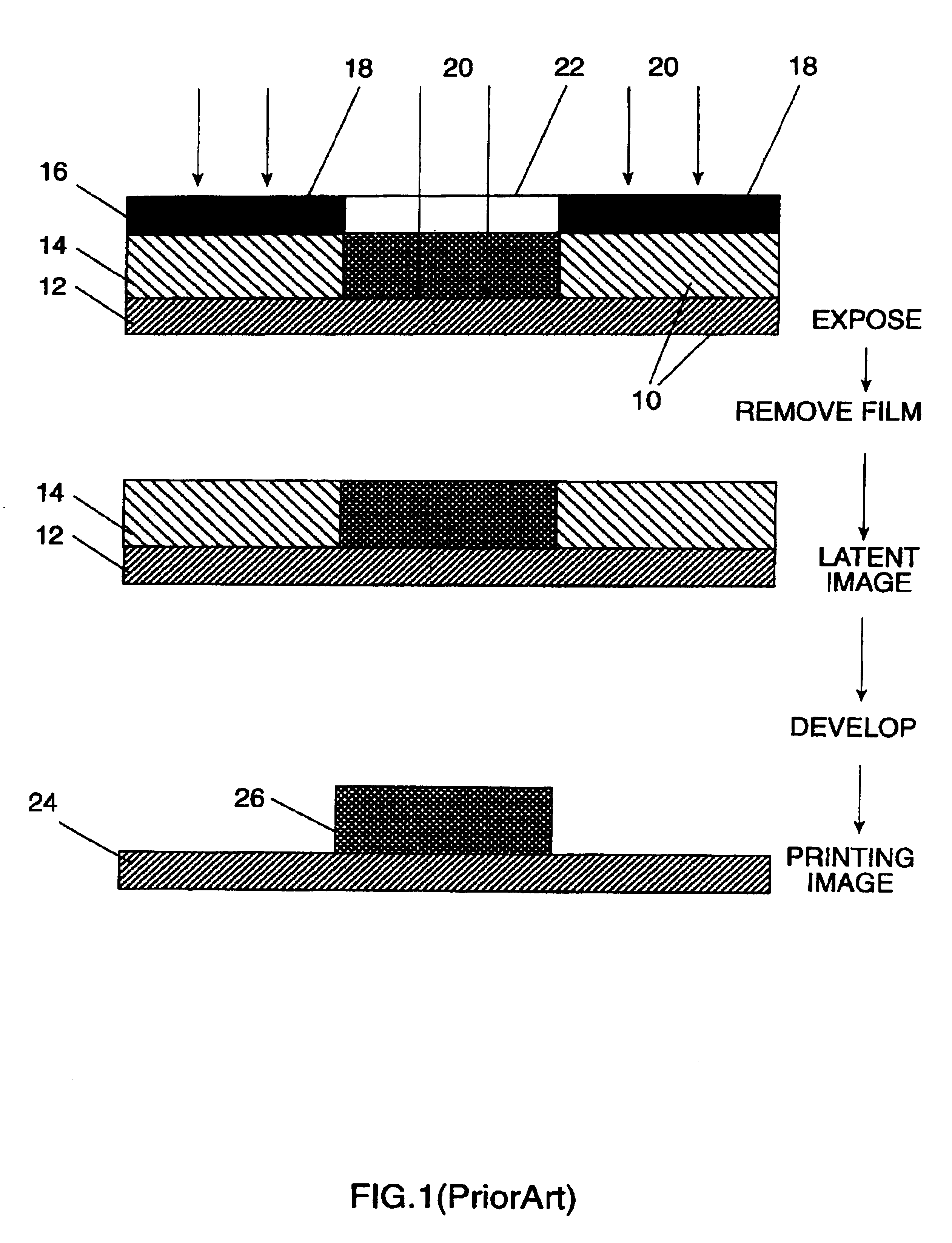
[0032]Referring now to the drawings, FIG. 1 shows, in a series of enlarged sectional views, an example of the widely-used prior art process of platemaking with pre-sensitized plates. Printing plate 10 comprises a grained, anodized aluminum substrate 12 and an emulsion coating 14, containing a prepolymer, photoinitiator, binder, resin, and dyes or pigments. A film negative 16 acts as a negative mask in emulsion-to-emulsion contact with plate 10 and is flood-exposed with UV light 20. The path of UV light 20 to the photosensitive, prepolymeric emulsion coating 14 is blocked by deposits of blackened, light-opaque silver 18. Thus, UV light 20 reaches emulsion coating 14 only in transparent area 22 of the negative image. Exposure of emulsion coating 14 under transparent area 22 activates the photoinitiator component of emulsion coating 14 and initiates polymerization. Negative masking film 16 is then removed from plate 10 which is then passed through a plate processor (not shown) usually ...


PUM

PropertyMeasurementUnit
Percent by massaaaaaaaaaa
Fractionaaaaaaaaaa
Weightaaaaaaaaaa

Abstract

An offset plate sensitive to UV or visible light, prepared simply and imaged digitally therewith in a CTP method, and also processed in a simple manner. The plate is provided as a photopolymer plate with increased sensitivity, and is used in a simple imaging-on-press system, using the surface of a lithographic printing cylinder itself as a plate substrate. The method of preparing the printing plate begins by applying a photosensitive liquid coating to the substrate, digitally imaging the coated substrate, using an actinic light source to polymerize portions of the liquid coating in accordance with the imaging, and washing the liquid.

Description

FIELD OF THE INVENTION[0001]The present invention generally relates to computer-to-plate (CTP) offset lithographic printing, and more particularly, to a novel method for producing an inexpensive and simple, offset printing plate which is digitally-imaged using actinic light.BACKGROUND OF THE INVENTION[0002]Offset lithographic printing has remained a most popular method of printing for many years. An important reason for this is the relative ease with which offset lithographic printing plates can be produced. Currently, the most widely-used method for plate preparation has remained that which utilizes specially-prepared masking films through which pre-sensitized printing blanks are selectively hardened or softened (according to the chemistry of the plate) by exposure to ultra-violet light. The plate then undergoes a development process, during which the more soluble regions of the plate (which may be the exposed or the unexposed areas) are washed away. A detailed description of the s...

Claims


Application Information

Patent Timeline
IPC IPC(8): B41C1/10G03F7/027G03F7/18B41M1/06B41M1/00G03F7/00G03F7/16
CPCG03F7/18G03F7/027
Inventor FIGOV, MURRAY
Owner KODAK IL
Learn More