
Optically written display

Inactive Publication Date: 2005-05-24
UNIV OF CENT FLORIDA RES FOUND INC
View PDF30 Cites 52 Cited by
  • Summary
  • Abstract
  • Description
  • Claims
  • Application Information

AI Technical Summary

Benefits of technology

[0007]The first objective of the present invention is to provide an inexpensive methods and systems for forming two dimensional and three dimensional displays.
[0010]The fourth object of this invention is to provide for optically written projection display methods and systems that can directly write an entire image at one time without having to form an image one pixel at a time or one line at a time.
[0013]The seventh object of this invention is to provide a single laser source such as a laser diode to efficiently excite two colors with the same pump wavelength.
[0014]The eigth object of this invention is to provide a single laser source such as a laser diode to efficiently excite three colors with the same pump wavelength.
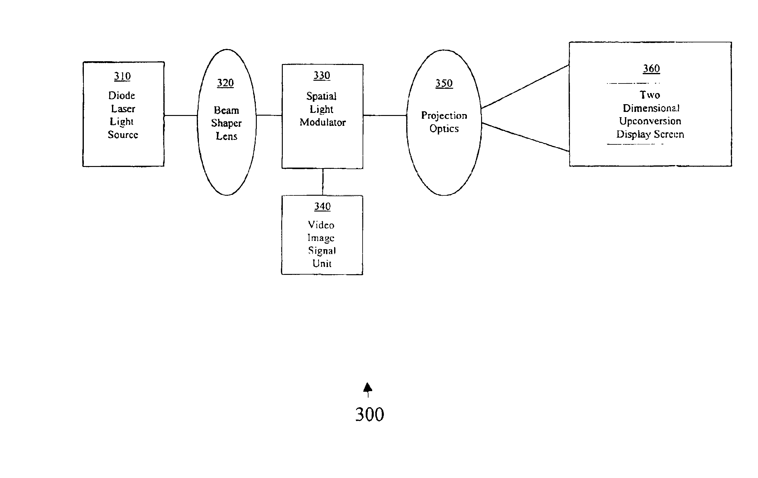
[0017]Optically written projection display(OWPD) embodiments are also disclosed, which can be more efficient electrically and cost less to manufacture than CRT(cathode ray terminals) and conventional projection televisions, by using novel combinations with scanners and modulators allowing for the simultaneous splitting and modulating of generated beams in addition to designs employing electro-optic and acousto optic modulators and scanners. The additional modifications allow for applications for high end projection televisions such as HDTV(high definition television) and movie screen applications that do not use raster type scanning techniques.
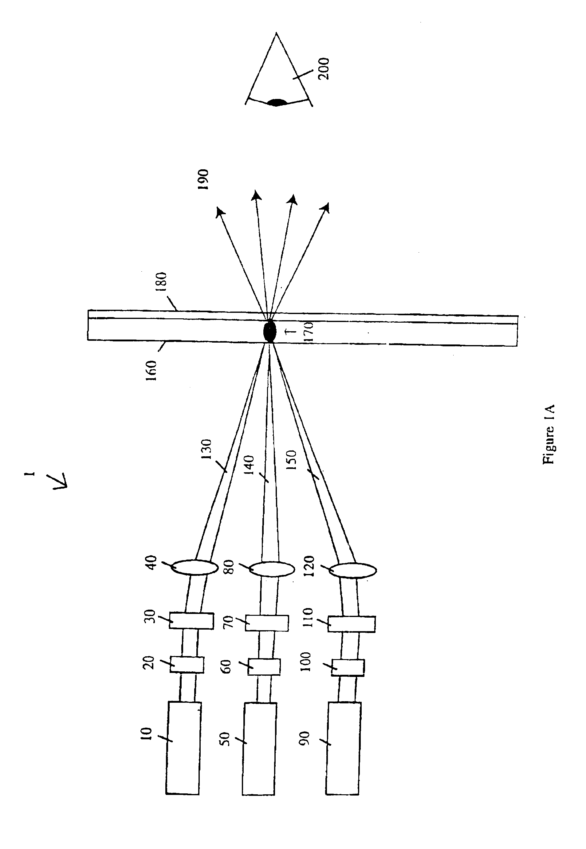
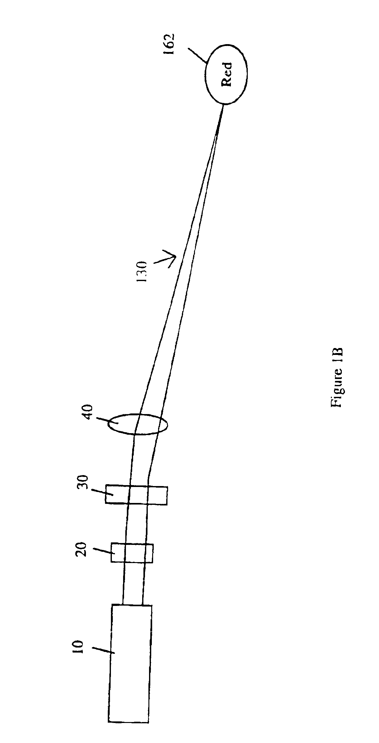
[0020]The light sources for the optically written projection displays can be a single laser diode for monochromatic displays, and can include up to three diodes for displays of red, green, and blue. The displayed image can be formed from reflecting three laser sources each having different wavelengths off the modulator,(or through it in a transmissive modulator), to each of the three different types of particles in the display medium. Infrared light can be absorbed by the particles in the pixels in the display. The particles in the pixels become excited and can emit visible radiation. Specifically, blue light can be efficiently generated by Yb,Tm:YLF(yttrium lithium fluoride) when pumped with diode laser light having a wavelength of approximately 958 to approximately 959 nm, green visible light can be efficiently generated by Yb,Er:NYF(sodium yttrium fluoride) when pumped with diode laser light having a wavelength of approximately 976 nm, and red visible light can be efficiently generated by Yb,Er:KYF(potassium yttrium fluoride) or Yb, Ef:YF3 when pumped with diode laser light having a wavelength of approximately 973.5 nm to approximately 976 nm.

Problems solved by technology

However, monochromatic does not offer the detail such as shown using red, green and blue colors.
The devices described can be expensive and complicated to manufacture, can have a narrow angular view ranges with low brightness.
However, for the single display media, Downing '403 uses nanometer sized particles, column 4, lines 33+, column 9, lines 42-45, which would inherently be difficult to form, handle and disperse in a display medium.

Method used


Image

  • Optically written display
  • Optically written display
  • Optically written display

Examples


Embodiment Construction

[0048]Before explaining the disclosed embodiments of the present invention in detail it is to be understood that the invention is not limited in its applications to the details of the particular arrangements shown since the invention is capable of other embodiments. Also, the terminology used herein is for the purpose of description and not of limitation.

[0049]Below described FIGS. 1A-7 are described in detail in U.S. application Ser. No. 09 / 976,921 filed Oct. 12, 2001 which is a Divisional Application of U.S. application Ser. No. 09 / 448,657 filed Nov. 24, 1999, which claims priority to U.S. Provisional Application 60 / 109,837 filed by the same subject inventors and assignee as the subject invention on Nov. 25, 1998, both of which are incorporated by reference and which are further described below. Additionally, this invention is a Continuation-In-Part of U.S. application Ser. No. 09 / 919,131 filed Jul. 31, 2001, and U.S. application Ser. No. 09 / 919,130 filed Jul. 31, 2001, by the sam...


PUM

PropertyMeasurementUnit
Fractionaaaaaaaaaa
Fractionaaaaaaaaaa
Fractionaaaaaaaaaa

Abstract

Two, three dimensional color displays having uniform dispersion of red, green and blue visible light emitting micron particles. Pumping at approximately 976 nm can generate green and red colors having an approximately 4% limit efficiency. One source can generate three colors with approximately limit efficiency. Modulators, scanners and lens can move and focus laser beams to different pixels forming two dimensional color images. Displays can be formed from near infrared source beams that are simultaneously split and modulated with micro electro mechanical systems, spatial light modulators, liquid crystal displays, digital micromirrors, digital light projectors, grating light valves, liquid crystal silicon devices, polysilicon LCDs, electron beam written SLMs, and electrically switchable bragg gratings. Pixels containing: Yb,Tm:YLF can emit blue light, Yb,Er(NYF) can emit green light, and Yb,Er:KYF and Yb,Ef:YF3 can emit red light.

Description

[0001]This invention claims the benefit of priority to U.S. Provisional Application 60 / 342,578 filed Dec. 26, 2001, and this invention is a Continuation-In-Part of U.S. application Ser. No. 09 / 976,921 filed Oct. 12, 2001 now U.S. Pat. No. 6,501,590, which is a Divisional Application of U.S. application Ser. No. 09 / 448,657 filed Nov. 24, 1999, now U.S. Pat. No. 6,327,074, which claims priority to U.S. Provisional Application 60 / 109,837 filed by the same subject inventors and assignee as the subject invention on Nov. 25, 1998, and this invention is a Continuation-In-Part of U.S. application Ser. No. 09 / 919,131 filed Jul. 31, 2001 now U.S. Pat. No. 6,654,161, and U.S. application Ser. No. 09 / 919,130 filed Jul. 31, 2001 now U.S. Pat. No. 6,844,387, and this invention was partially funded under U.S. Army Contract DAAD199910220.FIELD OF INVENTION[0002]This invention relates to displays, and in particular to methods and apparatus for forming an optically written projection display encompas...

Claims


Application Information

Patent Timeline
IPC IPC(8): C09K11/02C09K11/77
CPCC09K11/02C09K11/7773G03B21/60G03B21/2033Y10S501/904
Inventor BASS, MICHAELEICHENHOLZ, JASONRAPAPORT, ALEXANDRA
Owner UNIV OF CENT FLORIDA RES FOUND INC
Learn More