
Three-dimensional molding apparatus and three-dimensional molding method

a three-dimensional molding and molding apparatus technology, applied in the direction of additive manufacturing processes, manufacturing tools, electric/magnetic/electromagnetic heating, etc., can solve the problems of deterioration of shape accuracy and strength of the resultant three-dimensional molding article, affecting the quality of three-dimensional molding, and accelerating the molding speed of the hinges. achieve the effect of short tim

Inactive Publication Date: 2005-05-24
MINOLTA CO LTD
View PDF5 Cites 118 Cited by
  • Summary
  • Abstract
  • Description
  • Claims
  • Application Information

AI Technical Summary

Benefits of technology

"The present invention is a three-dimensional molding apparatus for forming a three-dimensional molded article by biding a powder material. The apparatus includes a layer formation device for sequentially forming a layer of a powder material, a binder applying device for applying a binder which will harden in response to a certain energy to a selected region in the layer of the powder material, and an energy supply device for supplying the certain energy to the binder applied to the powder material, wherein a bound body of the powder material is formed by the binder to harden in response to the certain energy supplied from the energy supply device. The apparatus can form a three-dimensional molded article in short time. The present invention is also directed to a three-dimensional molding method. The technical effect of the present invention is to provide a three-dimensional molding technique capable of generating a three-dimensional molded article in short time."

Problems solved by technology

However, in the three-dimensional molding apparatus mentioned above, since a binder which will harden when dried is used, a time for drying the binder to bind the powder material after application of the binder is required, which hinders speed up of molding.
In addition, in the case of applying the above-mentioned binder using an inkjet head, the hole diameter of the nozzle portion is small (not more than 20 μm), so that when a binder having a strong adhesive strength is used, the binder will easily harden due to drying and likely to cause blocking.
If such a malfunction occurs, the powder material in the region where the binder is to be applied will not be bound by the blocked nozzle, which will lead deterioration of shape accuracy and strength of a resultant three-dimensional molded article.
For this reason, in the case where an inkjet head is used, only a binder of weak adhesive strength can be used, and the strength of a finished three-dimensional molded article becomes low.
In addition, in such a case, only a powder material which will bind by means of a binder having a weak adhesive strength can be used, so that the flexibility in selecting the powder material is limited.

Method used


Image

  • Three-dimensional molding apparatus and three-dimensional molding method
  • Three-dimensional molding apparatus and three-dimensional molding method
  • Three-dimensional molding apparatus and three-dimensional molding method

Examples


Embodiment Construction

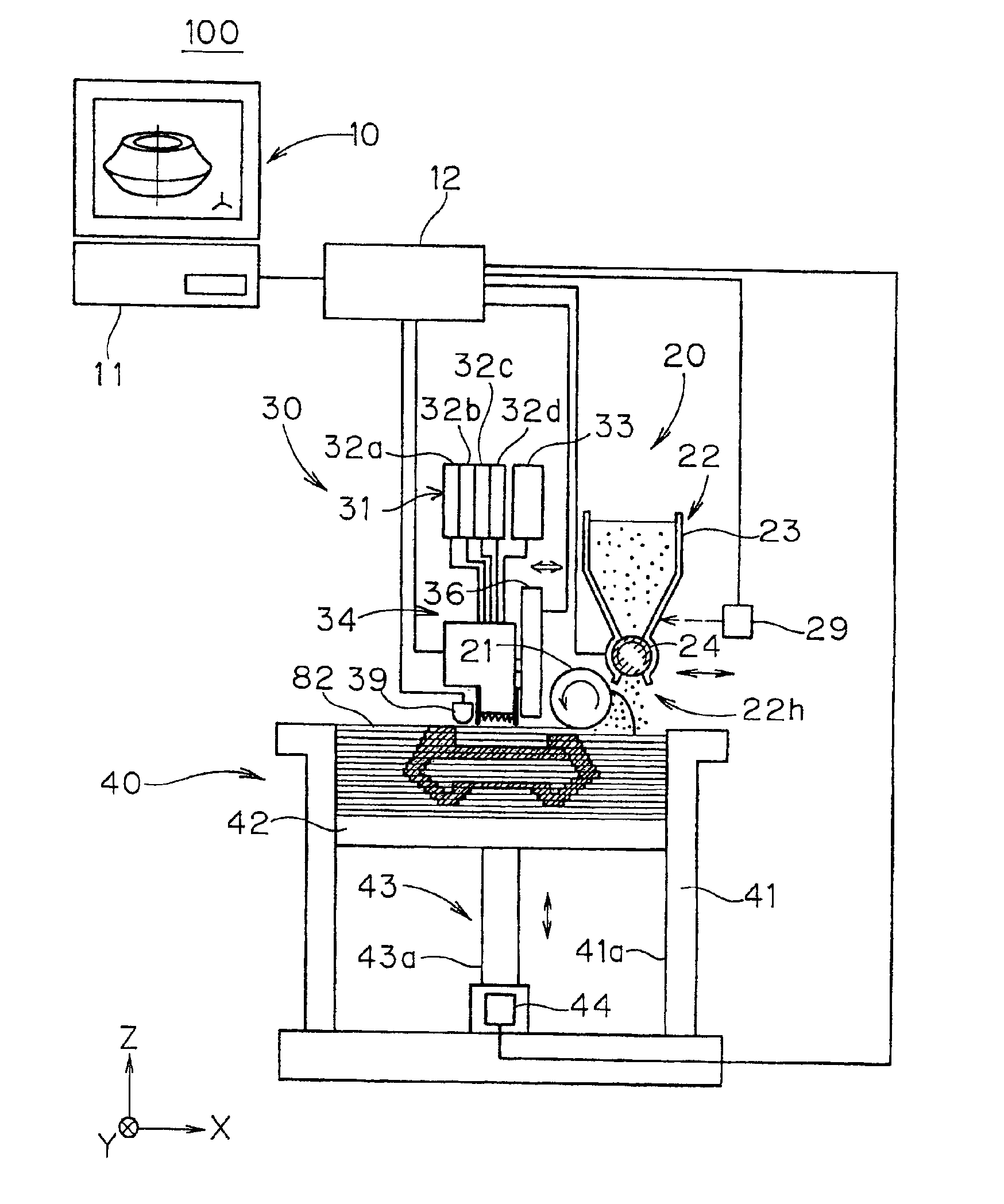
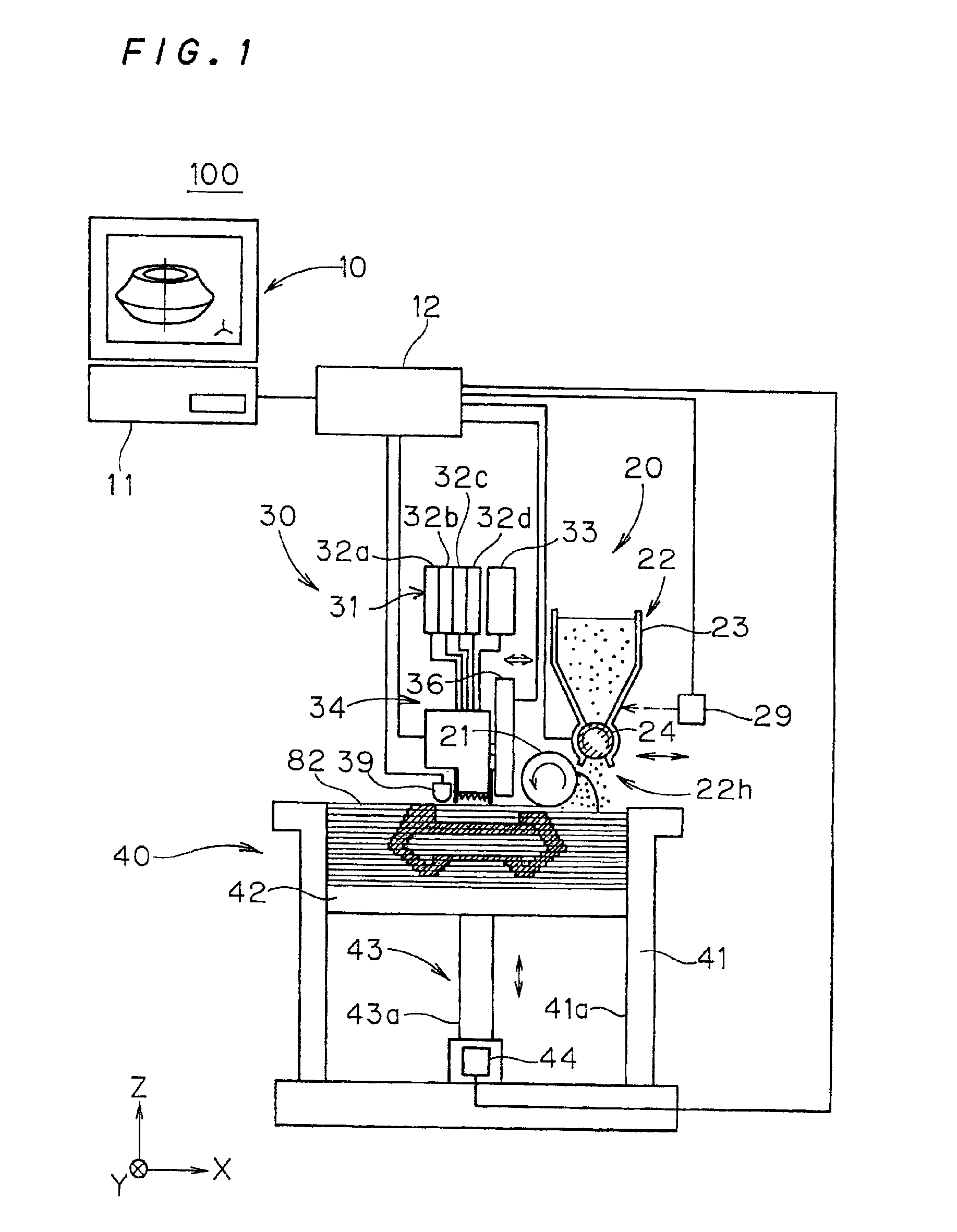
[0054]FIG. 1 is a view showing an essential configuration of a three-dimensional molding apparatus 100 according to a first preferred embodiment of the present invention.

[0055]The three-dimensional molding apparatus 100 comprises a control section 10 and thin layer formation section 20 and a binder applying section 30 and a molding section 40.

[0056]The control section 10 includes a computer 11 and a drive control section 12 which is electrically connected with the computer 11.

[0057]The computer 11 can be a general desk top type computer or the like having a CPU, a memory and the like incorporated therein. This computer 11 generates shape data of a molded article of three-dimensional shape and outputs cross section data obtainable by slicing the molded article into a multiplicity of parallel thin cross sections, to the drive control section 12.

[0058]The drive control section 12 functions as control means for individually driving the thin layer formation section 20, the binder applyin...


PUM

PropertyMeasurementUnit
energyaaaaaaaaaa
colorsaaaaaaaaaa
light energyaaaaaaaaaa

Abstract

To provide a three-dimensional molding technique capable of generating a three-dimensional molded article in short time.In a three-dimensional molding apparatus, a powder material is allowed to drop via an opening while moving a thin layer formation section in the +X direction, thereby forming a powder layer on a molding stage. With respect to a selected region in the powder layer, a binder of ultraviolet-ray hardening resin is discharged from a head section. Then, the powder layer is irradiated with ultraviolet rays from an ultraviolet irradiation section, making the ultraviolet-ray hardening resin applied on the powder layer harden to thereby bind the powder material. By repeating this operation with respect to the powder layer which is sequentially formed, a three-dimensional molded article is formed. In this way, since an ultraviolet-ray hardening resin is used as a binder and a powder material can be bound rapidly by ultraviolet irradiation, it is possible to generate a three-dimensional molded article in short time.

Description

[0001]This application is based on application Nos. 2001-30888, 2001-96147 and 2001-157751 filed in Japan, the contents of which are hereby incorporated by reference.BACKGROUND OF THE INVENTION[0002]1. Field of the Invention[0003]The present invention relates to a three-dimensional molding technique, and more particularly to a three-dimensional molding technique for generating a three-dimensional molded article by allowing a powder material to bind by applying a binder.[0004]2. Description of the Background Art[0005]As conventional three-dimensional molding apparatuses, there is known an apparatus whereby a binder which will harden when dried is discharged to a layer of powder material by means of inkjet and the like, and a bound body of the powder material is sequentially formed to mold a three-dimensional molded article. In such a three-dimensional molding apparatus, the operations as will be described below will be carried out for generating a three-dimensional molded article, fo...

Claims


Application Information

Patent Timeline
Patent Type & Authority Patents(United States)
IPC IPC(8): B29C67/00B29C35/08
CPCB29C67/0077B29C67/0081B29C35/0805B29K2995/0021B29C2035/0827B29C64/153B29C64/165H04N1/52
Inventor KUBO, NAOKINORITA, TOSHIOMIYAZAKI, MAKOTOWADA, AKIRA
Owner MINOLTA CO LTD
Learn More