
Paper machine clothing and a method of producing the same

Active Publication Date: 2005-05-24
HEIMBACH GMBH & CO KG
View PDF16 Cites 10 Cited by
  • Summary
  • Abstract
  • Description
  • Claims
  • Application Information

AI Technical Summary

Benefits of technology

[0008]The first object is achieved according to the invention in that the longitudinal and transverse filaments are fused at crossing points to each other and / or to parts joining them as a result of heating which is restricted to said crossing points. The basic concept of the invention is therefore to heat the longitudinal and transverse filaments to their melting temperature, and thus to fuse them together, only at the crossing points where they are to be joined to each other. The temperature of the other regions of the filaments remains below the melting point of the filament material. Therefore, the latter does not undergo any change in structure or shape, so that as a whole the filament structure which is determined by the superposition of the layers is retained. Paper machine clothing which comprises a filament lay-up, and which is distinguished by its high dimensional stability and its low manufacturing costs due to the use of single-component filaments, is thus provided for the first time. Single-component filaments are to be understood to be filaments which homogeneously consist of one material, where the material can also be a copolymer, with the sole proviso that homogeneity is achieved.
[0009]Compared with knitted and woven fabrics, the paper machine clothing according to the invention has the advantage of a high degree of flexibility with regard to the number of layers, the filament density and the choice of material. Moreover, costly textile machines, such as weaving and knitting machines, are not necessary for manufacture. Furthermore, machines such as these restrict the width of paper machine clothing produced on them. Filament lay-ups are not subject to a restriction such as this, i.e. they can be produced in practically any width. Moreover, the thermofixing which is necessary for woven fabrics can be dispensed with if the filaments have previously been subjected to adequate thermal treatment.
[0010]Temporary fixing can also be effected by additionally positively attaching the longitudinal and transverse filaments to each other at crossing points. Each joint can consist of an aperture in one filament and of a projection, which fits suitably therein, on the crossing filament. The joint can also be formed, however, by the filaments having apertures which are mutually aligned at the crossing points, and through which a pin passes, e.g. a round bolt or a rivet made of plastics or metal. Moreover, a positive attachment such as this provides support for the fused joint between the filaments or between the apertures and projections or pins, and ensures even better fixing at the crossing points.
[0011]It is particularly preferred if the longitudinal and transverse filaments are formed as flat filaments with a rectangular cross-section. In this manner, surface contact occurs at the crossing points, and the area over which the filaments are fused to each other is considerably enlarged and is thus stronger. A range from 2 to 20 mm, preferably from 8 to 12 mm, has proved to be an advantageous width for the longitudinal and transverse filaments. The thickness should range between 0.3 and 2 mm, preferably between 0.6 and 1.2 mm, wherein the transverse filaments should have a thickness which as a maximum is the same as that of the longitudinal filaments.
[0021]According to a further feature of the invention, provision is made for the longitudinal and transverse filaments firstly to be joined to each other at crossing points, using an adhesive and / or with a positive fit, before they are fused to each other. The joint at the crossing points is thereby further strengthened. Moreover, the position of the longitudinal and transverse filaments can be fixed by adhesive bonding and / or by positive attachment before the fusion operation, which is an advantage when the filament-containing product which is thus formed is moved through an apparatus by means of which thermal energy is applied.

Problems solved by technology

Furthermore, machines such as these restrict the width of paper machine clothing produced on them.

Method used


Image

  • Paper machine clothing and a method of producing the same
  • Paper machine clothing and a method of producing the same
  • Paper machine clothing and a method of producing the same

Examples


Embodiment Construction

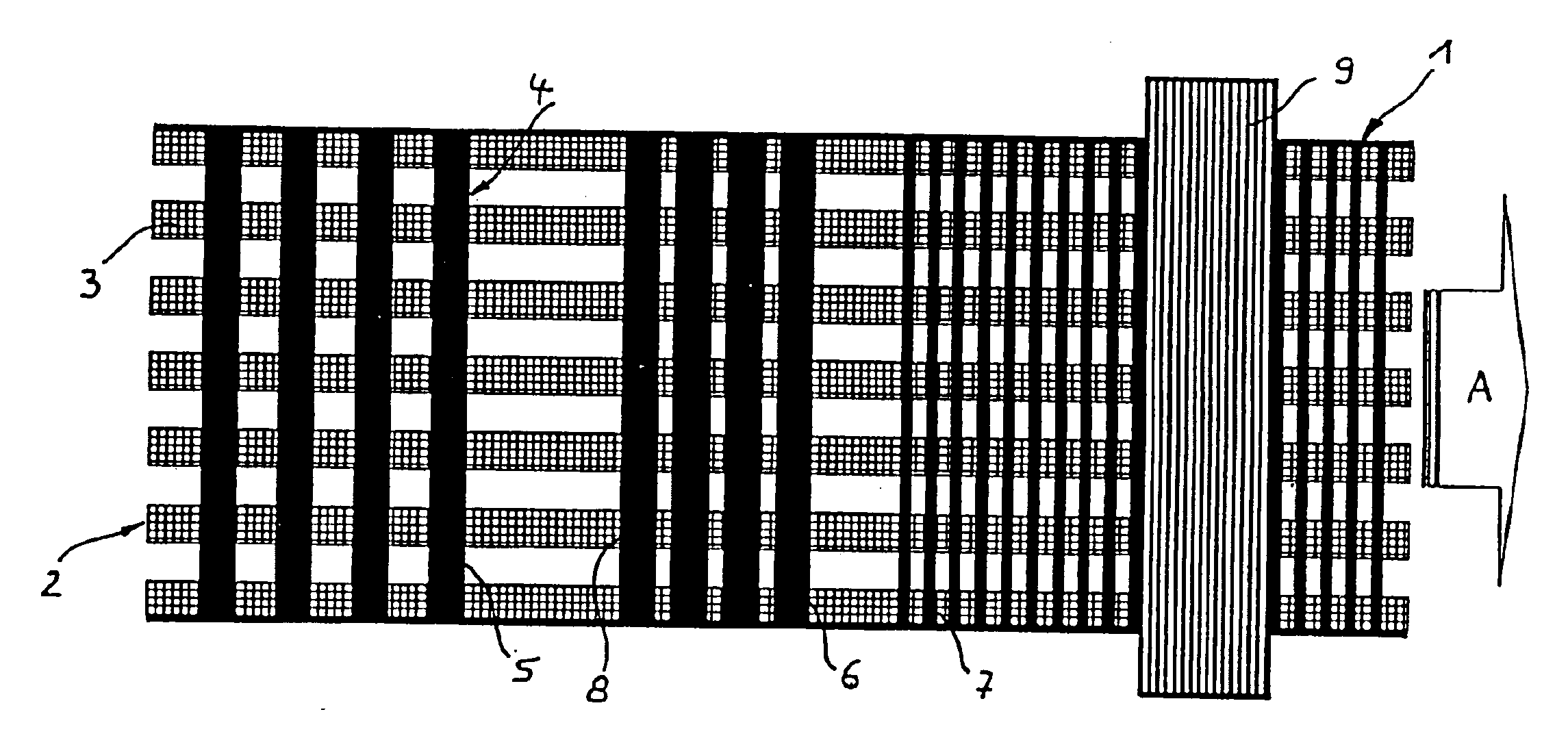
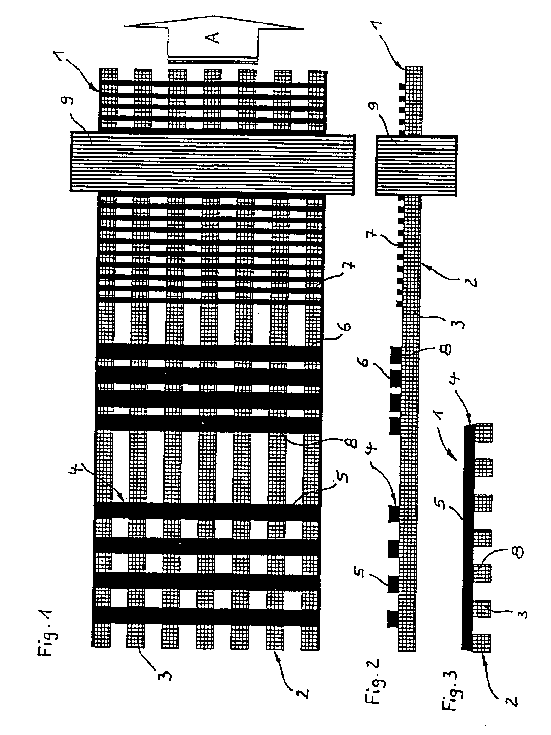
[0038]The paper machine clothing 1 illustrated in FIGS. 1 to 3 consists of a filament lay-up, the lower layer 2 of which is formed by longitudinal filaments—denoted by 3, for example. As can be seen in particular from FIG. 3, the longitudinal filaments 3 have a rectangular cross-section and are at identical spacings from each other. For the production process, the left-hand ends of the longitudinal filaments are wound on a filament beam, which is not shown here. A second beam, which is likewise not shown here, but on which the finished paper machine clothing 1 is wound up, is provided on the right-hand side. The paper machine clothing 1 is moved in this direction (arrow A).

[0039]An upper layer 4 comprising mutually parallel transverse filaments—denoted by 5, 6, 7, for example—is laid on the lower layer 2. The transverse filaments 5 are disposed at a wide spacing which substantially corresponds to the spacing between the longitudinal filaments 3, whilst the transverse filaments 6 are...


PUM

PropertyMeasurementUnit
Widthaaaaaaaaaa
Widthaaaaaaaaaa
Widthaaaaaaaaaa

Abstract

This invention relates to porous paper machine clothing (1, 11, 21) for de-watering a paper web in a paper machine, comprising a filament lay-up made of at least one layer (2, 12, 22) of longitudinal filaments (3, 13, 23) and at least one layer (4, 14, 24) of transverse filaments (5, 6, 7; 15; 25) which cross the longitudinal filaments (3, 13, 23), wherein the longitudinal and transverse filaments (3, 13, 23; 5, 6, 7; 15; 25) are single-component filaments, which is characterised in that the longitudinal and transverse filaments (3, 13, 23; 5, 6, 7; 15; 25) are fused at crossing points (8, 16, 27) to each other and / or to parts (17, 18, 19) joining them as a result of heating to the melting temperature which is restricted to said crossing points (8, 16, 27).The invention further relates to a method of producing porous paper machine clothing such as this.

Description

FIELD OF THE INVENTION[0001]This invention relates to porous paper machine clothing for de-watering a paper web in a paper machine, particularly as a paper machine felt or drying screen, comprising a filament lay-up made of at least one layer of longitudinal filaments and at least one layer of transverse filaments which cross the longitudinal filaments, wherein the longitudinal and transverse filaments are single-component filaments.BACKGROUND OF THE INVENTION[0002]Porous paper machine clothing comprises long, wide belts which circulate in different parts of a paper machine and on which the paper web is conveyed through the paper machine. In the first part, which is termed the sheet forming section, a fibrous pulp is deposited on the paper machine clothing, whereupon a web of fibrous material is formed. This is dewatered through the paper machine clothing. The paper machine clothing consists of a textile filament product which is sufficiently porous for the liquid which originates f...

Claims


Application Information

Patent Timeline
IPC IPC(8): D21F1/00D04H3/14D21F1/10D21F7/08
CPCD21F1/0027D21F1/0036D21F1/0054D21F1/0081Y10T428/24091Y10T428/24273Y10T428/2817Y10T428/24785Y10T428/24074Y10S162/90Y10T428/249923
Inventor BEST, WALTERMOLLS, CHRISTIAN
Owner HEIMBACH GMBH & CO KG
Learn More