Rear projection screens and light filters with conformable coatings and methods of making the same
a technology of rear projection screen and light filter, which is applied in the direction of labelling articles, diffuse elements, paper/cardboard containers, etc., can solve the problems of poor angularity of rear projection screen, undesirable speckle pattern, and limited construction of screen and filter, so as to improve light throughput, improve angularity, and reduce speckle
- Summary
- Abstract
- Description
- Claims
- Application Information
AI Technical Summary
Benefits of technology
Problems solved by technology
Method used
Image


Examples
example 1
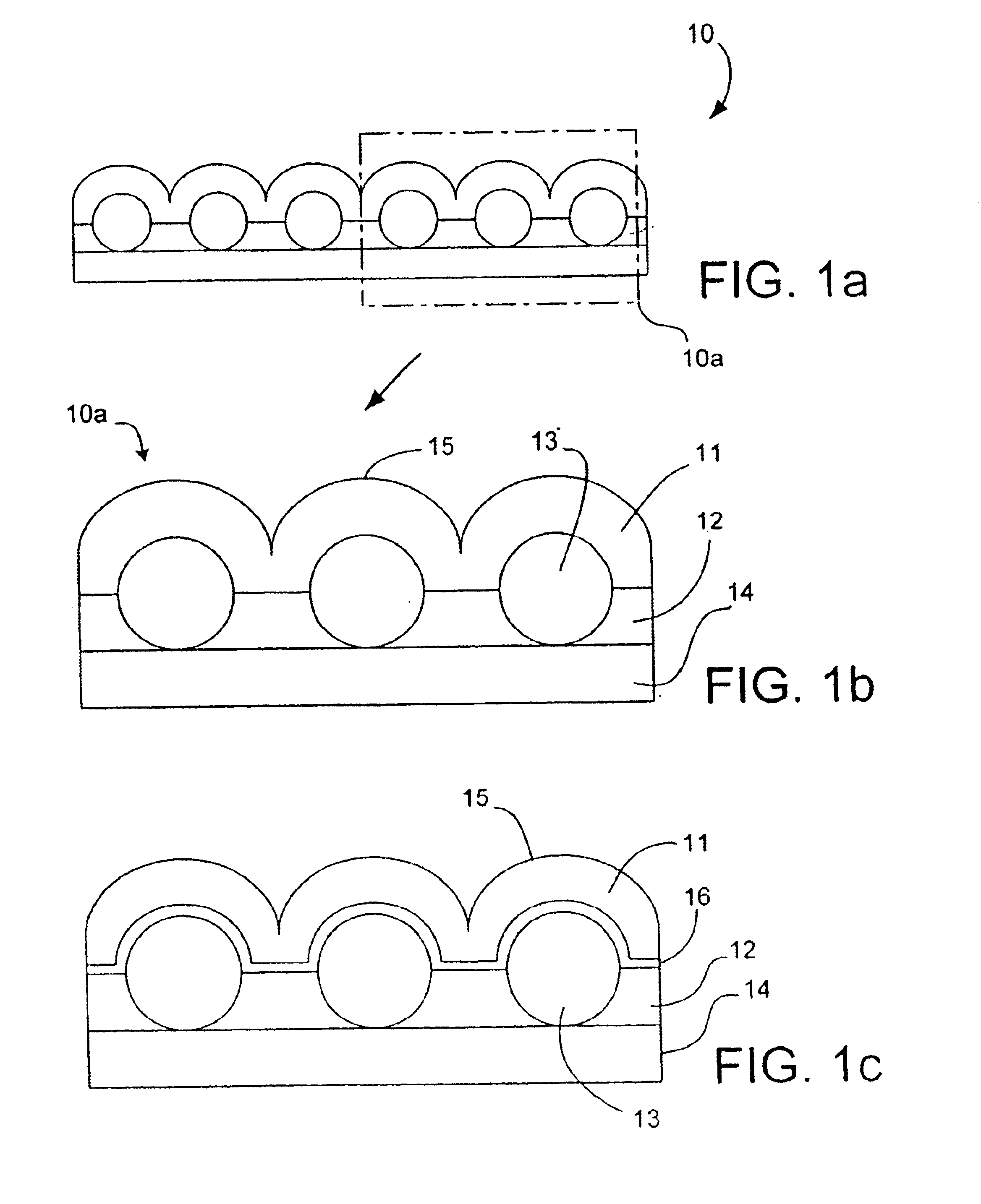
[0046]A 75 micron (3 ml) layer of polyethylene terephthalate (SH-71 Polyester film from SKC America) is laminated to a 75 micron (3 mil) layer of polymethylmethacrylate. (Acrylic HI-7 from ICI). A 10 micron (0.4 mil) layer of black polyvinyl butyral (Butvar B-90 from Solutia containing 6% carbon black) is placed on top of the polymethylmethacrylate. Glass microspheres having a refractive index of 1.80 and having an average diameter of 52 microns are embedded into the polyvinylbutyral forming a light tunnel to make construction 1. A paper facestock coated with low density polyethylene and having a matte surface is obtained (e.g., Felix Schoeller Technical Paper F315L), and onto the layer of polyethylene (matte surface) is coated a 10 micron (0.4 mil) thick layer of clear polyvinylbutyral (Butvar B-90 from Solutia) to make construction 2. Construction 1 and 2 are pressed together (black polyvinylbutyral layer with exposed microspheres of construction 1 to the clear polyvinylbutyral la...
example 2
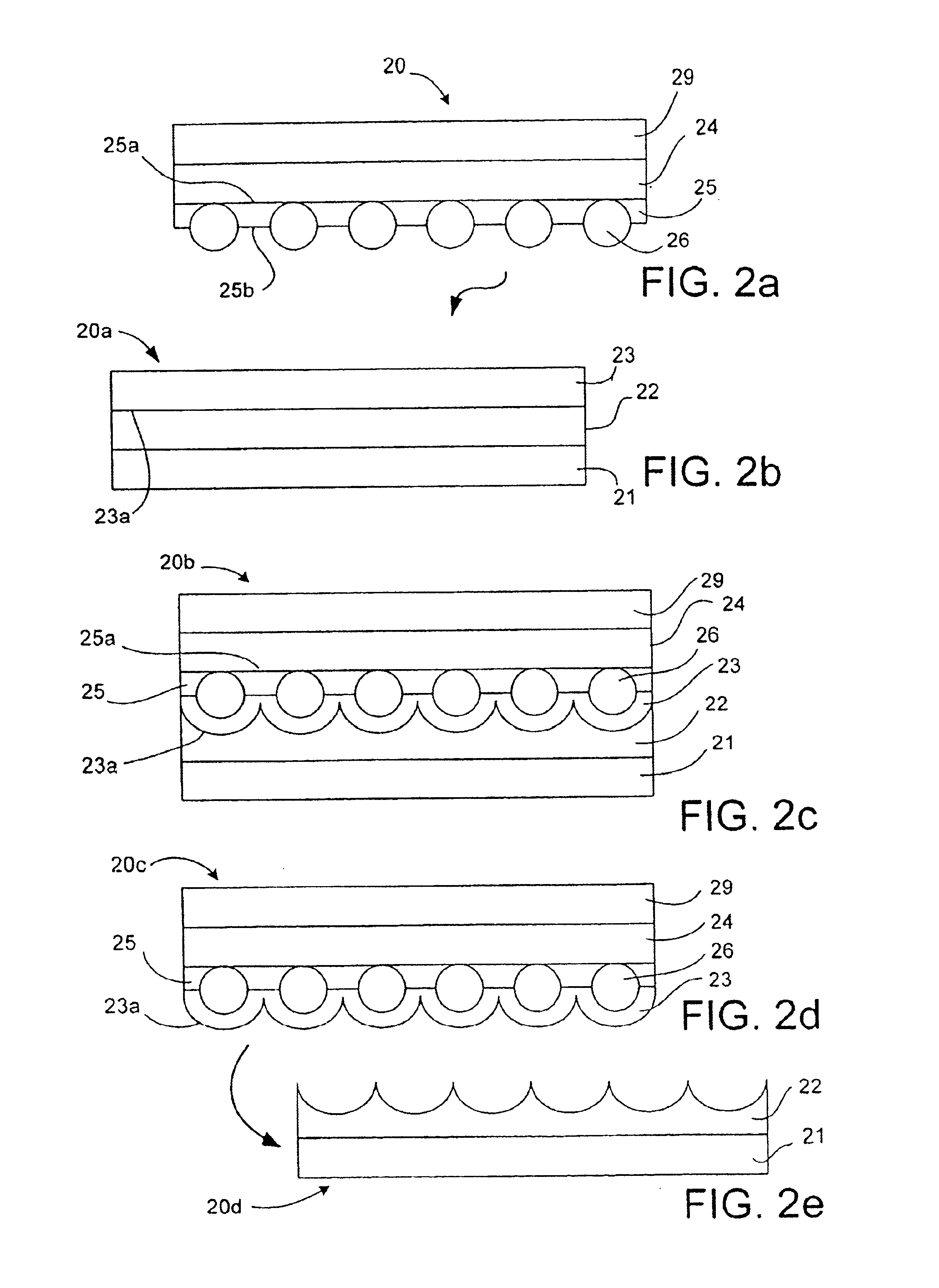
[0047]A paper facestock coated with low density polyethylene and having a matte finish such as Felix Schoeller Technical Paper F315L is coated with 0.4 mil (10 microns) of polyvinyl butyral (Butvar B-90), and the glass microspheres of Example 1 are embedded into the polyvinyl butyral layer. A second construction is prepared which comprises a 75 micron (3 mil) layer of polyethylene terephthalate (SH-71 from SKC America) coated with 75 microns (3 mils) of polymethylmethacrylate (MI-7 from Rohm & Haas) and 10 microns (0.4 ml) of black polyvinyl butyral (Butvar B-79 containing 6% carbon black). These two constructions are combined by laminating the exposed layer of black polyvinylbutyral to the layer of clear polyvinylbutyral containing the glass microspheres. Lamination is accomplished at a pressure of about 100 psi and at a temperature of about 285° F. (140° C.). After cooling, the paper and polyethylene layers are removed thereby exposing the back surface of the conformed layer of cl...
example 3
[0048]This example illustrates a light filter of the present invention which does not include an optically clear support layer as present in Examples 1 and 2 above. A first construction is prepared comprising a 75 micron layer of polyethylene terephthalate and 10 microns of a black thermoplastic polyurethane P-9827 from Morton containing 6% carbon black. A second construction is prepared which comprises a paper coated with 35 microns of low density polyethylene having a matte finish on the exposed surface followed by coating with a 10 micron layer of clear polyvinylbutyral. Glass microspheres of Example 1 are then embedded into the polyvinylbutyral. The two constructions are then laminated together by bringing the layer of clear polyvinylbutyral into contact with the layer of black polyurethane whereby the exposed microspheres are embedded in the thermoplastic urethane layer to the extent that the microspheres touch and / or perforate the surface of the black polyurethane layer which ...
PUM
| Property | Measurement | Unit |
|---|---|---|
| transparent | aaaaa | aaaaa |
| refractive index | aaaaa | aaaaa |
| transparent | aaaaa | aaaaa |
Abstract
Description
Claims
Application Information
 - R&D
- Intellectual Property
- Life Sciences
- Materials
- Tech Scout
- Unparalleled Data Quality
- Higher Quality Content
- 60% Fewer Hallucinations
Browse by: Latest US Patents, China's latest patents, Technical Efficacy Thesaurus, Application Domain, Technology Topic, Popular Technical Reports.
© 2025 PatSnap. All rights reserved.Legal|Privacy policy|Modern Slavery Act Transparency Statement|Sitemap|About US| Contact US: help@patsnap.com