
Structure and method of attaching a heat transfer part having a compressible interface

a heat transfer part and compressible technology, applied in the field of elastomeric material composition, can solve the problems of heat transfer potential, operational hot spots, and accelerate seepage, and achieve the effects of improving overall thermal conductivity, increasing contact pressure, and uniform pressur

Inactive Publication Date: 2005-05-24
TICONA POLYMERS INC
View PDF26 Cites 71 Cited by
  • Summary
  • Abstract
  • Description
  • Claims
  • Application Information

AI Technical Summary

Benefits of technology

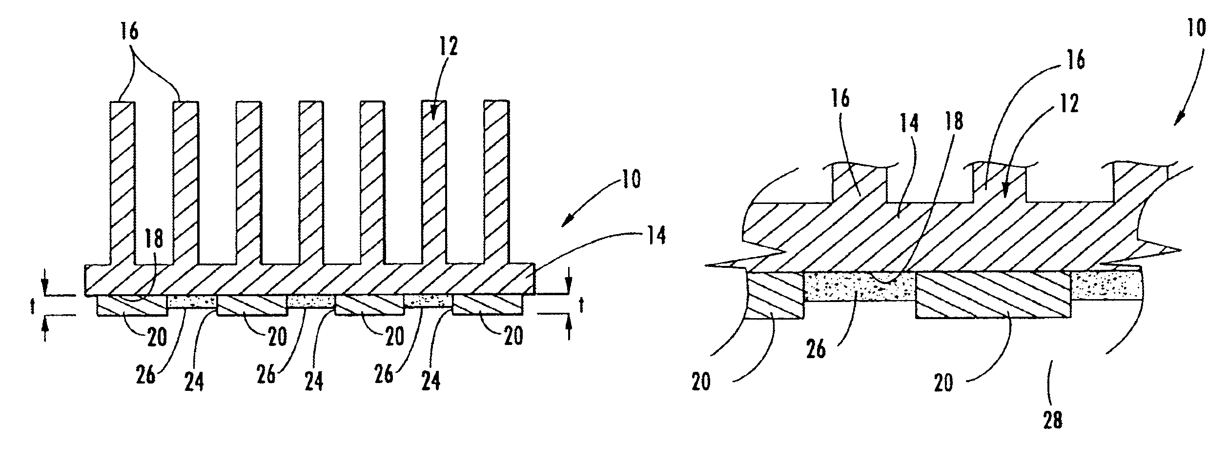
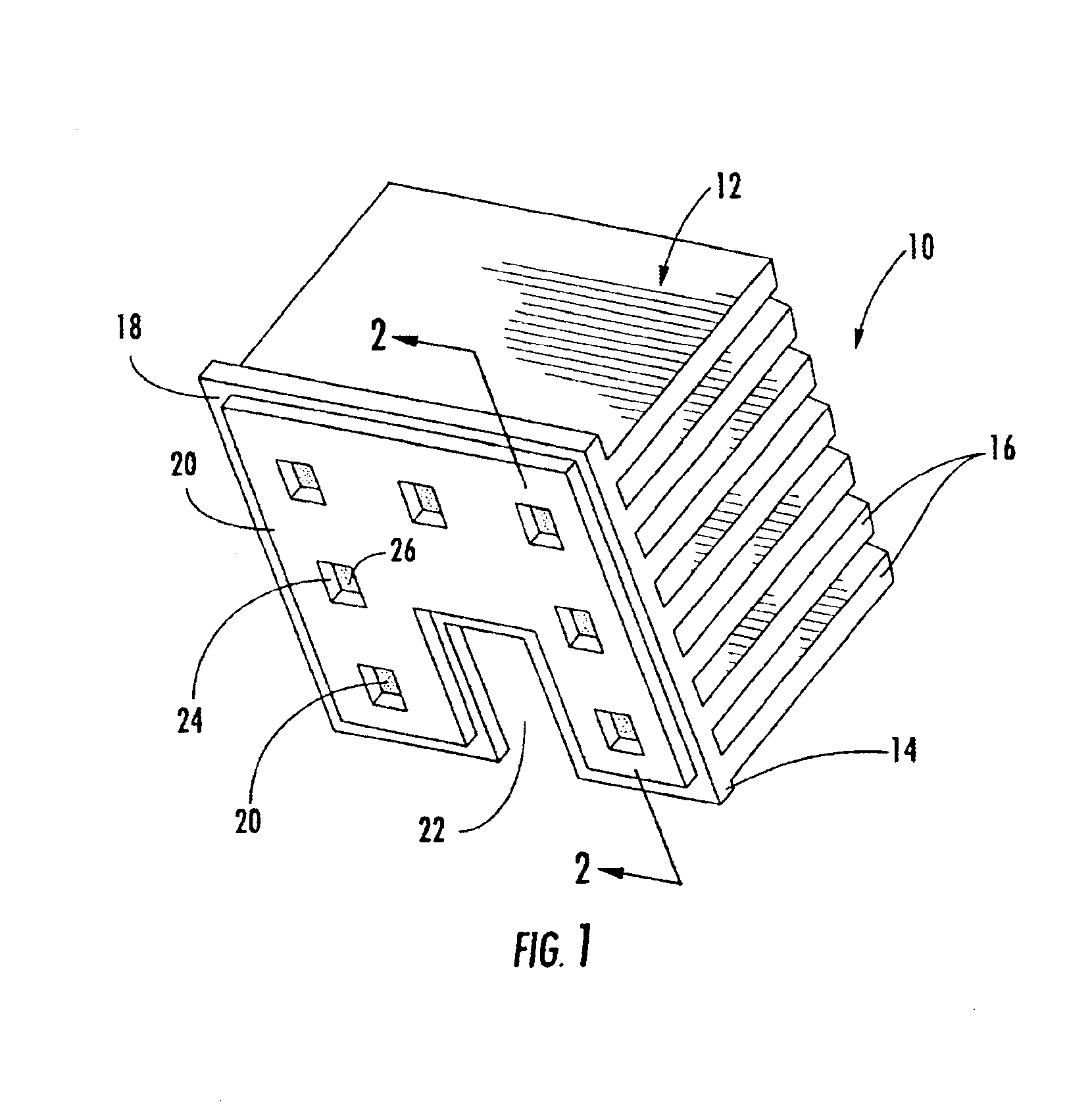
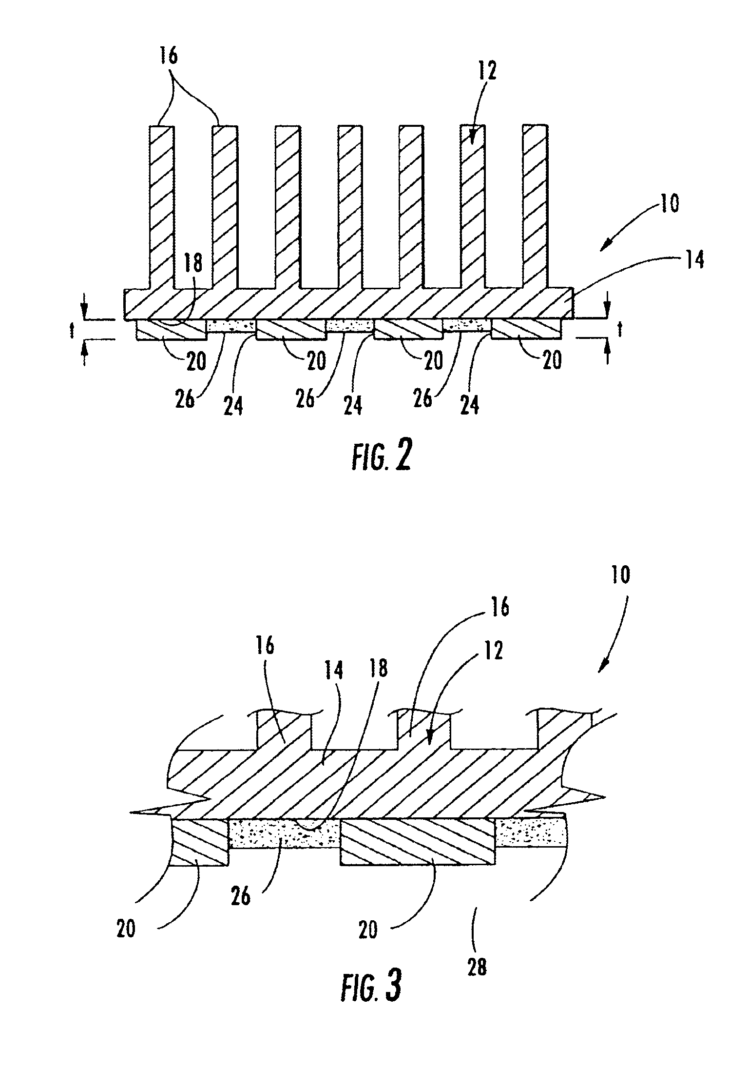
[0010]The second component of the present invention is a pressure sensitive adhesive component. The adhesive is applied adjacent to the thermal transfer element and may be located in an alternating pattern throughout a base field of thermal transfer material. The adhesive component has a thickness that is less than the overall thickness of the thermal transfer material. When the heat dissipating device with the present invention applied is pressed into contact with a heat generating surface, pressure must be applied to compress the elastomeric material and allow the adhesive to come into contact with the heat generating surface. Once brought into contact and bonded, the adhesive holds the heat generating and heat dissipating surfaces in firm contact with the pre-loaded, compressed elastomeric thermal transfer layer therebetween. When the interface of the present invention is installed, the elastomer is compressed until the adhesive makes contact with the mating surface thus increasing the contact pressure between all of the heat transfer surfaces and improving overall thermal conductivity through the entire assembly.
[0011]The present invention provides for a complete thermal interface solution and eliminates the requirement for the use of additional clips and fasteners to maintain uniform pressure between the heat generating assembly and the heat dissipating surface as were requires in thermal interfaces of the prior art. The present invention therefore provides a superior interface while simplifying assembly and reducing assembly costs.
[0012]It is therefore an object of the present invention to provide a thermal interface assembly that enhances the dissipation of heat from a heat generating electronic component upon which the device is mounted. It is also an object of the present invention to provide a thermal interface assembly for use in an electronic device that is conformable and integrally formed on a heat-dissipating device that provides efficient heat transfer for a heat generating electronic component upon which the device is mounted. It is a further object of the present invention to provide an elastomeric integrally formed conformable thermal interface that includes a means for adhesively fastening the interface in a compressed position, eliminating the need for additional fastening means. It is yet another object of the present invention to provide a heat dissipation assembly as described above that passively provides heat transfer between a heat generating surface and a heat sink while having an integrally formed conformable interface and an integral adhesive that maintains the compression of the interface in order to fill any gaps or voids therebetween. It is a further object of the present invention to provide a conformable elastomeric thermal interface assembly for an electronic device that can be applied directly to complex geometries to accommodate a variety of device shapes.

Problems solved by technology

These imperfections and gaps between the mating surfaces often contain small pockets of air that can significantly reduce the heat transfer potential across the interface between the heat generating surface and the heat-dissipating device.
However, it has been found that the thermal greases exhibit poor adhesion to the surfaces of the heat sink and heat generating surface, thus effectively seeping out from between the heat sink and the heat-generating surface, causing air voids to form between the two surfaces that eventually result in operational hot spots.
Moreover, excessive pressure placed upon the heat sink by the mechanical fasteners accelerates this seepage from between the heat sink and the surface of the heat-generating surface.
It has been reported that excessive squeeze out of polysiloxane oils can evaporate and recondense on other sensitive parts of the surrounding microcircuits.
The recondensed oils lead to the formation of silicates that potentially interfere with the function of the microprocessor, eventually causing failure of the system.
The precut films solve the problems associated with greases but do not provide adequate intimate contact required for optimum heat transference between the heat generating source and the heat sink.
The added step of cutting preforms and manually applying the pad adds cost to the assembly process.
Further, while these known interface materials, are suitable for filling undesirable air gaps, they are generally are less thermally conductive than the heat sink member thus detracting from the overall thermal conductivity of the assembly.
An additional drawback to most of the above noted interface materials is that they require a machined heat sink be secured to a heat generating surface or device using mechanical clips or screws adding to the complexity and assembly time for the overall assembly.
The drawback in the prior art is that the use of an adhesive interface pad requires an additional fabrication / assembly step and introduces an additional layer of material along the heat dissipation pathway.
Further, as mentioned above, since all of the materials within the assembly are different, optimum heat transfer cannot be achieved.

Method used


Image

  • Structure and method of attaching a heat transfer part having a compressible interface
  • Structure and method of attaching a heat transfer part having a compressible interface
  • Structure and method of attaching a heat transfer part having a compressible interface

Examples


Embodiment Construction

[0018]Referring now to the drawings, the heat dissipation assembly of the present invention is shown and illustrated generally as 10. The present invention is a heat dissipation assembly 10 that includes an integral interface structure and means for retaining the assembly in compressed relation to a heat generating device and a method of manufacturing the same. The assembly of the present invention 10 provides a unique interface structure that includes a compressible thermal interface that is applied to an interface surface of a heat-dissipating device and also includes integral means for retaining the heat dissipation device in operable relation to a heat generating device. The present invention maintains the thermal interface in proper compressed relation with out the requirement of additional fasteners.

[0019]Turning now to FIG. 1, the assembly 10 of the present invention is shown here, by way of example, in connection with a traditionally shaped heat sink device 12 having a base ...


PUM

PropertyMeasurementUnit
Fractionaaaaaaaaaa
Thicknessaaaaaaaaaa
Pressureaaaaaaaaaa

Abstract

The present invention discloses a thermal transfer interface having an integrally formed means for fastening and maintaining intimate thermal contact between a heat generating device and a heat-dissipating device. The interface of the present invention includes two components, a compressible thermal transfer component having a first thickness and an adhesive fastening component having a second thickness that is less than the first. The first component, the thermal transfer element, includes a base polymer matrix compound that is loaded with a thermally conducting filler that imparts thermally conductive properties to the net shape moldable material. The polymer base matrix is preferably a highly compressible material such as an elastomer. The second component of the present invention is a pressure sensitive adhesive component. The adhesive is applied adjacent to the thermal transfer element or in an alternating pattern throughout a base field of thermal transfer material. The adhesive component has a thickness that is less than the overall thickness of the thermal transfer material. When, the heat dissipating device with the present invention applied is pressed into contact with a heat generating surface the elastomer is compressed and maintained in the compressed state by the pressure sensitive adhesive material.

Description

CROSS-REFERENCE TO RELATED APPLICATIONS[0001]This application is related to and claims priority from earlier filed provisional patent application No. 60 / 335,064 filed Oct. 24, 2001.BACKGROUND OF THE INVENTION[0002]The present invention relates generally to an elastomeric material composition for use in joining heat-dissipating devices with heat generating electronic devices and a method for manufacturing the same. More particularly, this invention relates to a new compressible thermal interface assembly having an integral interface and fastening means that is applied directly to the heat dissipation device at the time of manufacture. The present invention includes a interface composition that contains thermally conductive filler material in a conformable elastomeric matrix and an integral means for adhering the heat dissipation device to a heat-generating surface thereby compressing the interface composition to form an improved heat sink device with an integral, compressible thermal...

Claims


Application Information

Patent Timeline
IPC IPC(8): F28F13/00
CPCF28F13/00Y10T29/4935
Inventor PANEK, JEFFREY
Owner TICONA POLYMERS INC
Learn More