High-frequency amplifier, feed-forward amplifier and distortion compensating amplifier

Inactive Publication Date: 2005-05-17
MITSUBISHI ELECTRIC CORP
View PDF12 Cites 14 Cited by
  • Summary
  • Abstract
  • Description
  • Claims
  • Application Information

AI Technical Summary

Benefits of technology

[0025]A high-frequency amplifier according to the present invention includes subsidiary amplifying means for performing an amplifying operation for a high-frequency signal distributed and input only in a case where an instantaneous electric power of the high-frequency signal is high, and main amplifying means for always performing an amplifying operation for a high-frequency signal distributed and input. The high-frequency signal amplified by the subsidiary amplifying means is injected into an output side of the main amplifying means, and the high-frequency signal amplified by the main amplifying means is output. Therefore, an output load impedance can be changed in accordance with a change of an envelope of a modulated high-frequency signal. Accordingly, a high-frequency amplifier operated at a sufficiently high saturation electric power and an excellent efficiency can be provided by changing the output load impedance of the high-frequency amplifier in accordance with the change of the envelope caused by the modulation. In other words, a high-frequency amplifier operated at high efficiency even in a high back-off operation state, that is, in a low output electric power as compared with a saturation electric power can be provided.

Problems solved by technology

As a result, a large amount of disturbance wave is leaked to an adjacent channel, the transmitted high-frequency signal is degraded, and transmission error is increased.
In contrast, on the load impedance condition corresponding to the high saturation electric power, no great portion of the instantaneous electric power of the high-frequency signal is cut off, but the efficiency in the high-frequency amplifier is undesirably lowered.
Because of the above-described reasons, it is difficult to obtain a high-frequency amplifier in which the load impedance condition corresponding to the high saturation electric power and the load impedance condition corresponding to the high efficiency are satisfied.
Therefore, though a high-frequency amplifier of a base station is required to amplify a high-frequency signal of a high crest factor at low distortion, the efficiency in the high-frequency amplifier is lowered due to the low maximum efficiency in the operation at the back-off of 10 dB.
Because the conventional high-frequency amplifier has the above-described configuration, a problem has arisen that it is difficult to obtain a high-frequency amplifier operated at a sufficiently high saturation electric power and an excellent efficiency while following the change of an envelop of a high-frequency signal.
Also, even though the change-over of the switch is performed at high speed, it is difficult to obtain a switch and a variable element which have characteristics of electric power resistance sufficiently possible to be used for an output circuit of a high-frequency amplifier and are operated at low loss.
As a result, a problem has arisen that an effect of the improvement of the efficiency is not sufficient.

Method used


Image

  • High-frequency amplifier, feed-forward amplifier and distortion compensating amplifier
  • High-frequency amplifier, feed-forward amplifier and distortion compensating amplifier
  • High-frequency amplifier, feed-forward amplifier and distortion compensating amplifier

Examples


embodiment 1

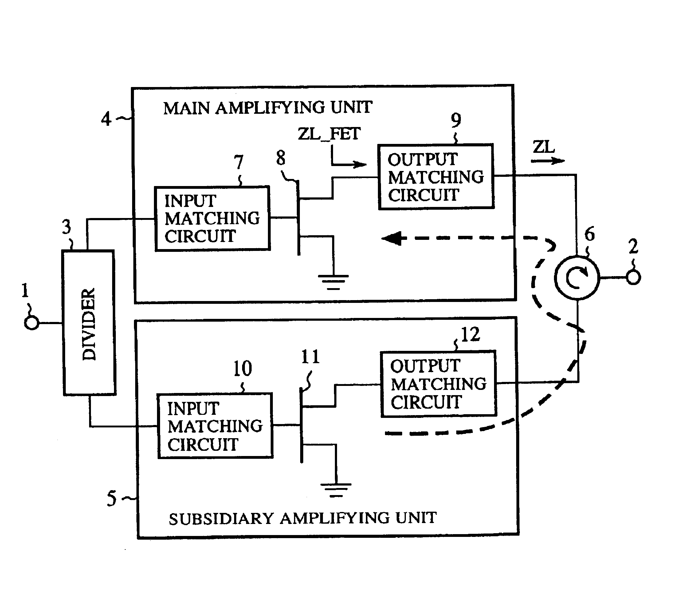
[0088]FIG. 5 is a view showing the configuration of a high-frequency amplifier according to a first embodiment of the present invention.

[0089]In FIG. 5, 1 indicates an input terminal to which a high-frequency signal is input. 2 indicates an output terminal from which the high-frequency signal is output. 3 indicates a divider (or first distributing means) in which the high-frequency signal input to the input terminal 1 is divided and distributed to two lines of two output sides. 4 indicates a main amplifying unit (or main amplifying means) connected to one output side of the divider 3. 5 indicates a subsidiary amplifying unit (or subsidiary amplifying means) connected to the other output side of the divider 3. 6 indicates a circulator. The circulator 6 is arranged so as to inject the high-frequency signal output from the subsidiary amplifying unit 5 into the output side of the main amplifying unit 4 and to inject the high-frequency signal output from the main amplifying unit 4 into t...

embodiment 2

[0113]FIG. 7 is a view showing the configuration of a high-frequency amplifier according to a second embodiment of the present invention. The constituent elements, which are the same as those shown in FIG. 5, are indicated by the same reference numerals as those of the constituent elements shown in FIG. 5.

[0114]In FIG. 7, 13 indicates a 90-degree hybrid (or second distributing means) in which two high-frequency signals having a phase difference of 90 degrees from each other are produced from the high-frequency signal of one line output from the divider 3 and are distributed to two lines respectively. 14A and 14B indicate two amplifying units (or first main amplifying means and second main amplifying means) in which the two high-frequency signals output from the 90-degree hybrid 13 are respectively amplified. 15 indicates a 90-degree hybrid (or a first 90-degree hybrid). In the 90-degree hybrid 15, the amplified high-frequency signal output from the subsidiary amplifying unit 5 is di...

embodiment 3

[0124]FIG. 8 is a view showing the configuration of a high-frequency amplifier according to a third embodiment of the present invention. The constituent elements, which are the same as those shown in FIG. 5, are indicated by the same reference numerals as those of the constituent elements shown in FIG. 5.

[0125]In FIG. 8, 16 indicates a variable attenuation unit (or first amplitude and phase adjusting means) in which an amplitude of the high-frequency signal passing the subsidiary amplifying unit 5 is adjusted. 17 indicates a variable phase shift unit (or first amplitude and phase adjusting means) in which a phase of the high-frequency signal passing the subsidiary amplifying unit 5 is adjusted. In the third embodiment, the variable attenuation unit 16 and the variable phase shift unit 17 are arranged between the subsidiary amplifying unit 5 and the circulator 6, and both an amplitude and a phase of the high-frequency signal output from the subsidiary amplifying unit 5 are adjusted.

[...


PUM


Abstract

A divider 3 for dividing and distributing a high-frequency signal input from an input terminal 1 to two output sides, a main amplifying unit 4, connected to one output side of the divider 3, for amplifying one high-frequency signal output from the divider 3, a subsidiary amplifying unit 5, connected to the other output side of the divider 3, for performing no operation in case of a low instantaneous electric power of the other high-frequency signal output from the divider 3 and amplifying the other high-frequency signal in case of a high instantaneous electric power of the other high-frequency signal and a circulator 6 for injecting the high-frequency signal amplified in the subsidiary amplifying unit 5 into the output side of the main amplifying unit 4 and injecting the high-frequency signal amplified in the main amplifying unit 4 into an output terminal 2 are arranged.

Description

TECHNICAL FIELD[0001]The present invention relates to a high-frequency amplifier operated at a high efficiency even in an operation state of high back-off, a feed-forward amplifier and a distortion compensating amplifier used for the high-frequency amplifier.BACKGROUND ART[0002]A high-frequency signal belonging to a communication band such as a very high frequency (VHF) band, an ultra-high frequency (UHF) band or a microwave band is modulated according to a modulation method such as quadrature phase shift keying (QPSK) or quadrature amplitude modulation (QAM).[0003]In general, an amplitude of the high-frequency signal is changed with time in every time period corresponding to a band of a modulation wave. In other words, an envelope of the high-frequency signal is changed with time. In cases where a plurality of signals are simultaneously amplified in a base station for mobile communication, an envelope of the high-frequency signal is changed with time.[0004]FIG. 1 is a view showing ...

Claims


Application Information

Patent Timeline
IPC IPC(8): H03F1/00H03F3/60H03F3/189H03F1/56H03F1/32H03F1/02H03F3/68H03F3/193
CPCH03F3/604H03F1/3223H03F1/565H03F3/193
Inventor NAKAYAMA, MASATOSHIHORIGUCHI, KENICHIIKEDA, YUKIOKUNUGI, SATOSHISAKAI, YUJI
Owner MITSUBISHI ELECTRIC CORP
Why Eureka
Try Eureka