
Belt-drive continuously variable transmission

a transmission and continuously variable technology, applied in the direction of driving belts, gearing elements, gearing, etc., can solve the problems of partial and excessive wear of the transverse elements, and lowering the coefficient of friction between the transverse element and the pulley. , to achieve the effect of improving the torque transmission capacity of the drive belt and lowering the coefficient of friction

Inactive Publication Date: 2005-05-17
NISSAN MOTOR CO LTD
View PDF16 Cites 16 Cited by
  • Summary
  • Abstract
  • Description
  • Claims
  • Application Information

AI Technical Summary

Benefits of technology

The present invention provides a new and improved belt-drive continuously variable transmission that solves the problem of partial and excessive wear of the transverse elements and lowering of the coefficient of friction between the drive belt and the pulley. The new transmission includes a drive pulley, a driven pulley, and a belt engaged with the drive pulley and the driven pulley. Each transverse element has converging side faces for contact with the pulleys, and each side face is protruded and curved towards the contact surface of the pulley. This design ensures that each transverse element can make uniform contact with the pulleys, reducing wear and tear and improving the transmission's torque capacity.

Problems solved by technology

A problem of a prior art belt-drive continuously variable transmission is that each transverse element of a drive belt cannot be brought into contact at the entire side face thereof with the contact surface of a pulley but only partially, thus causing partial and excessive wear of the transverse elements and lowering of the coefficient of friction between the transverse element and the pulley.
Due to this, the side faces 2f and 2f of each transverse element 2 are not brought into contact at the entirety but only partially, i.e., only at the hatched area X of each side face 2f as shown in FIG. 12, thus causing the above described problem of partial and excessive wear of the transverse elements and lowering of the coefficient of friction between the transverse element and the pulley.

Method used


Image

  • Belt-drive continuously variable transmission
  • Belt-drive continuously variable transmission
  • Belt-drive continuously variable transmission

Examples


first embodiment

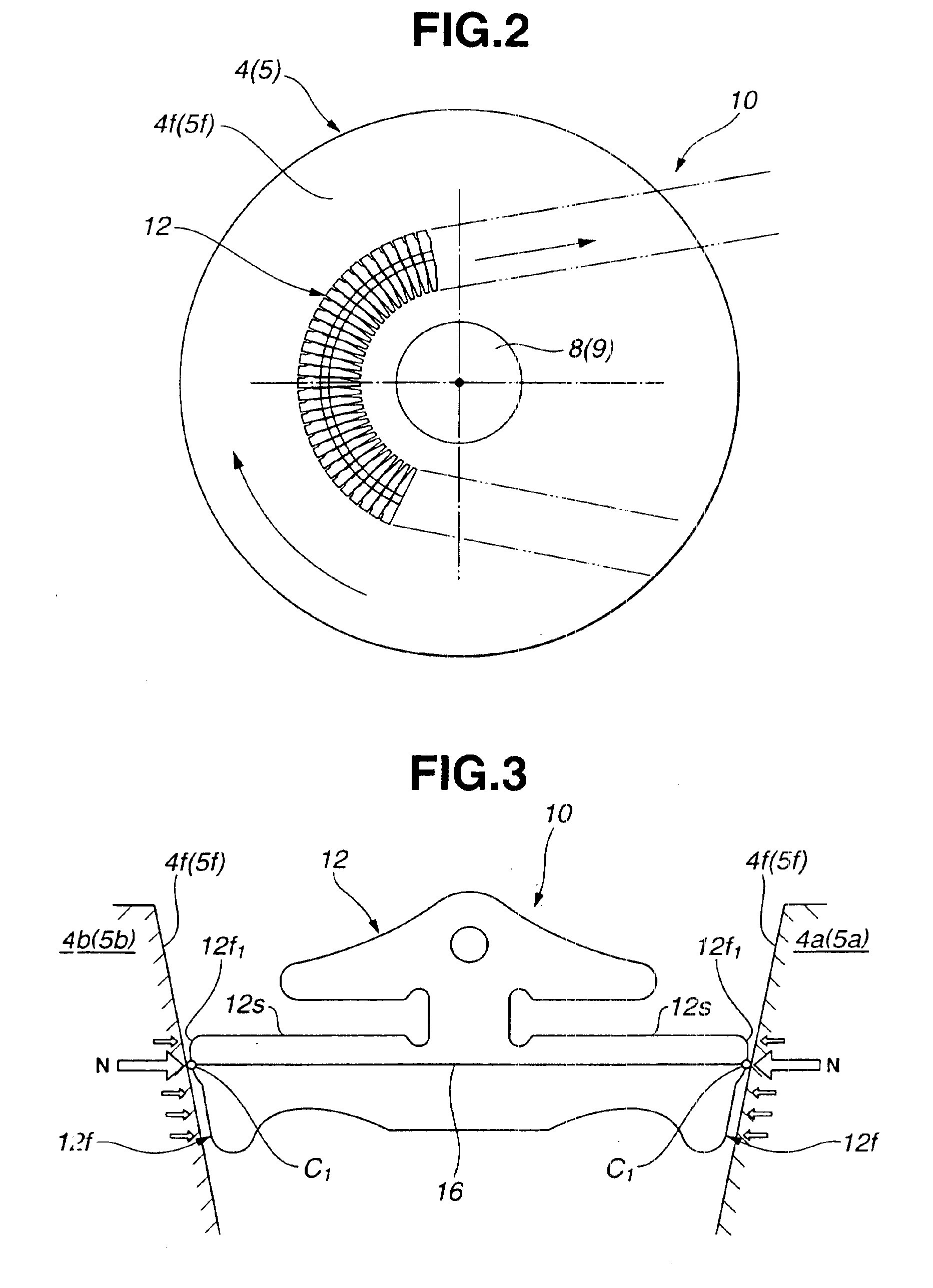
[0022]Referring first to FIGS. 1 to 3, a belt-drive continuously variable transmission according to the present invention includes a drive belt 10 wound around a primary pulley 4 and a secondary pulley 5 (refer to FIG. 9). Each pulley 4 (5) includes a conical disc 4a (5a) fixed to a rotatable shaft 8 (9) and a conical disc 4b (5b) movable axially on the rotatable shaft 8 (9). The primary pulley 4 may be connected to an engine (not shown) so as to serve as an input pulley or drive pulley and drive the secondary pulley 5 by way of the drive belt 10 so that the secondary pulley 5 serves as an output pulley or driven pulley.

[0023]In FIG. 2, the drive belt 10 is shown with an endless flexible band or carrier being omitted. As shown in FIGS. 1 and 2, the drive belt 10 includes a plurality of transverse elements 12 arranged closely (i.e., in such a manner as to be brought into contact with adjacent transverse elements 12) in the longitudinal direction thereof, and a pair of endless bands o...

second embodiment

[0033]FIG. 4 will be described more in detail with reference to FIG. 5.

[0034]Now, assuming that the contact surface 4f (5f) of the pulley 4 (5) is a planar surface made of steel and each side face 22f of the transverse element 22 is made up of a part of a cylinder of a radius R and made of steel, the half width b (mm) of the contact surface is calculated by the use of the formula of Hertz. That is, based on the maximum q (kgf / mm) of the thrust N supplied from the pulley 4 (5) to the transverse element 22, per unit length, the inclination β of the contact surface 4f (5f) (i.e., so-called half sheave angle) and the Young's modulus E (kgf / mm2) of steel, the half width b (mm) of the contact surface area of the side face 22f can be obtained by the following expression.

b=(1.522)×√{square root over ((q×cos β×R÷E))}≧dr

[0035]In this connection, assuming that dr is the distance between the contact surface of the transverse element 22 for contact with the endless carrier 13 (refer to FIG. 1),...

third embodiment

[0045]FIG. 6 shows a belt-drive continuously variable transmission according to the present invention.

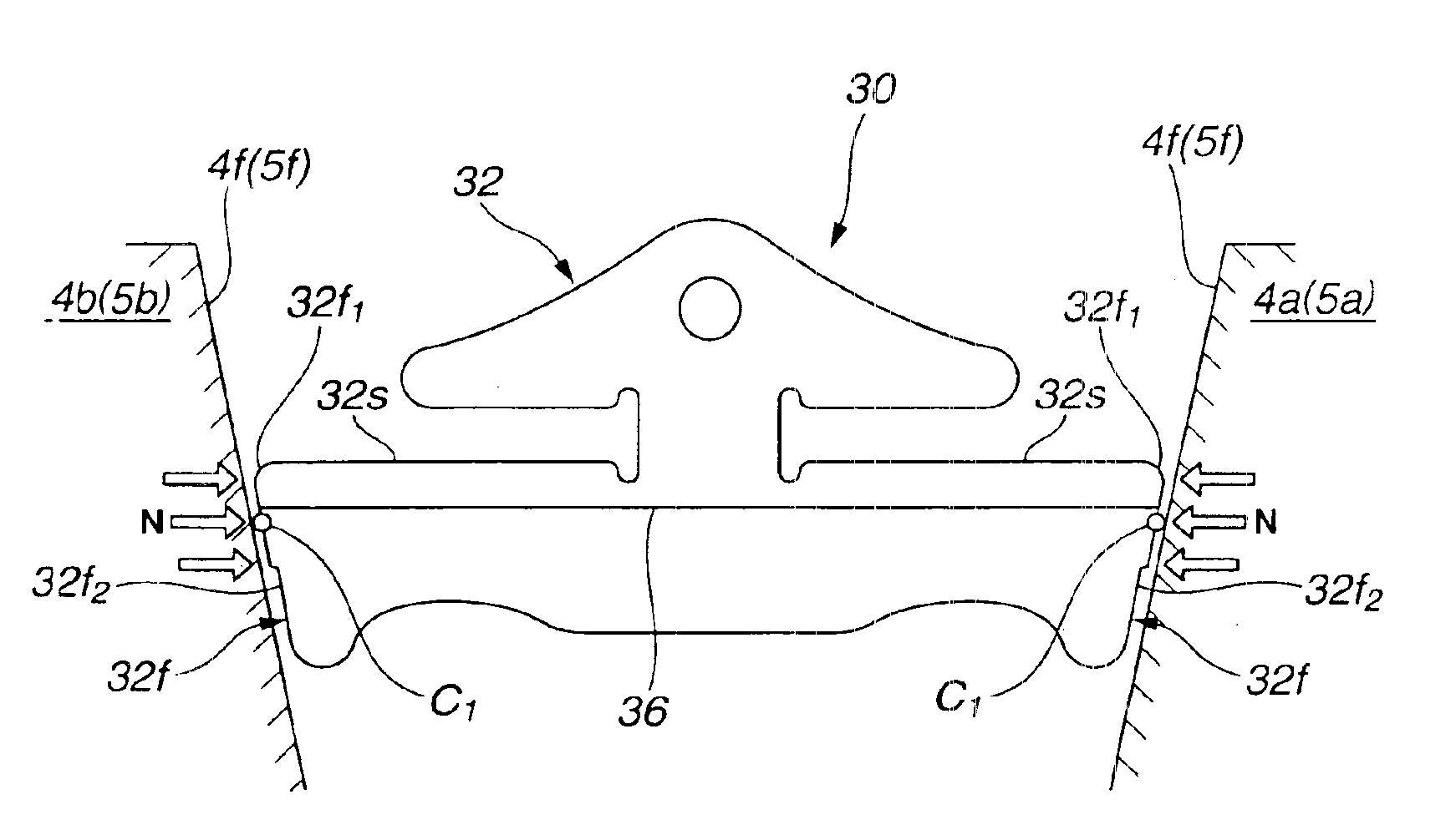
[0046]This embodiment differs from the first embodiment in that the side face 32f of the transverse element 32 is shaped so as to allow only the contact surface area 32f1 including a portion joining the rocking edge 36 when observed in FIG. 6, i.e., in a plan view of the transverse element 32, to protrude toward the contact surface 4f (5f) of the pulley 4 (5). Namely, the side face 32f is formed into a stepped shape. In this instance, it is desirable that the protruded contact surface area 32f1 is designed so as to be larger than the remaining area 32f2. Further, it is desirable that the edge of the transition between the contact surface area 32f1 and the remaining area 32f2 is chamfered.

[0047]Except for the above, this embodiment is substantially similar to the first embodiment described with reference to FIGS. 1 to 3 and can produce substantially the same effect.


PUM


Abstract

Provided is a belt-drive continuously variable transmission which comprises a pair of drive pulley and driven pulley, and a belt engaged with the pulleys. The belt includes an endless carrier and a plurality of transverse elements closely arranged on the carrier. Each transverse element has an edge and rotatable about the edge in the longitudinal direction of the belt and converging side faces for contact with contact surfaces of the pulleys. Each of the side faces is curved toward each of the contact surfaces in such a manner as to have, when each of the transverse elements is observed in a plan view, such a circular arc that is of a predetermined radius R and has a center located on a straight line perpendicular to each of the contact surfaces and extending through a point at which the edge and each of the contact surfaces meet.

Description

BACKGROUND OF THE INVENTION[0001]The present invention relates in general to belt-drive continuously variable transmissions, and particularly to a belt-drive continuously variable transmission of the kind wherein a belt includes an endless carrier and a plurality of transverse elements positioned transversely on the endless carrier, the transverse elements being arranged in such a manner that adjacent two of the transverse elements are held in contact with each other, each transverse element having a rocking edge and rotatable about the rocking edge in the longitudinal direction of the belt for thereby enabling the belt to be wound around a drive pulley and a driven pulley.[0002]A belt-drive continuously variable transmission is known from U.S. Pat. No. 5,439,422.SUMMARY OF THE INVENTION[0003]A problem of a prior art belt-drive continuously variable transmission is that each transverse element of a drive belt cannot be brought into contact at the entire side face thereof with the co...

Claims


Application Information

Patent Timeline
Patent Type & Authority Patents(United States)
IPC IPC(8): F16G5/00F16G5/16F16H9/12
CPCF16G5/163F16G5/16
Inventor KOBAYASHI, DAISUKE
Owner NISSAN MOTOR CO LTD
Learn More