
Method and system for controlling a complementary user interface on a display surface

Inactive Publication Date: 2005-05-10
OSTENDO TECH INC
View PDF107 Cites 145 Cited by
  • Summary
  • Abstract
  • Description
  • Claims
  • Application Information

AI Technical Summary

Benefits of technology

[0040]In yet another embodiment, a pixel mask technology is provided for supporting permitted applications to define, reserve, and use persistent display regions within the native desktop area of the display screen. These persistent display regions mask other output, thus preventing the output from the permitted applications to a persistent display region from being obscured by output from other (non-permitted) applications.
[0041]In yet another embodiment, a display-trap technology is provided to support a video card and driver independent mechanism for reducing the display area allocated to the desktop user interface, so that one or more parallel user interfaces can be displayed in the remaining area of the display screen.

Problems solved by technology

When the electron gun in a CRT retraces to the left of the screen or the top of the screen, it requires a significant amount of time relative to the presentation of a scanned line of data.
However, modern monitors have become much faster in their retrace speeds, leaving a significant amount of time when the electron gun need not be blanked, allowing a displayable border.

Method used


Image

  • Method and system for controlling a complementary user interface on a display surface
  • Method and system for controlling a complementary user interface on a display surface
  • Method and system for controlling a complementary user interface on a display surface

Examples


Embodiment Construction

[0044]Embodiments of the present invention provide methods and systems for displaying information on a display surface in a manner that complements the display metaphor and technology provided by a native operating system. Using techniques of embodiments of the present invention, a complementary user interface is made operable within an existing system or is provided as a stand-alone environment. The complementary user interface may coexist as one or more secondary graphical user interfaces (“GUIs”) with a primary user interface, such as conventional desktop GUI provided by the native operating system. The complementary user interface provided by such embodiments may be used, for example, to provide additional display screen real estate or to provide quick or continuous (“sticky”) access to selected applications. The complementary user interface may provide access to a wide variety of capabilities, including, for example, continuous access to a user's favorite network locations on, ...


PUM


Abstract

An alternate display content controller provides a technique for controlling a video display separately from and in addition to the content displayed on the operating system display surface. Where the display is a computer monitor, the alternate display content controller interacts with the computer utility operating system and hardware drivers to control allocation of display space and create and control one or more parallel graphical user interfaces in addition to the operating system desktop. An alternate display content controller may be incorporated in either hardware or software. As software, an alternate display content controller may be an application running on the computer operating system, or may include an operating system kernel of varying complexity ranging from dependent on the utility operating system for hardware system services to a parallel system independent of the utility operating system and capable of supporting dedicated applications. The alternate display content controller may also include content and operating software delivered over the Internet or any other LAN. The alternate display content controller may also be included in a television decoder / settop box to permit two or more parallel graphical user interfaces to be displayed simultaneously.

Description

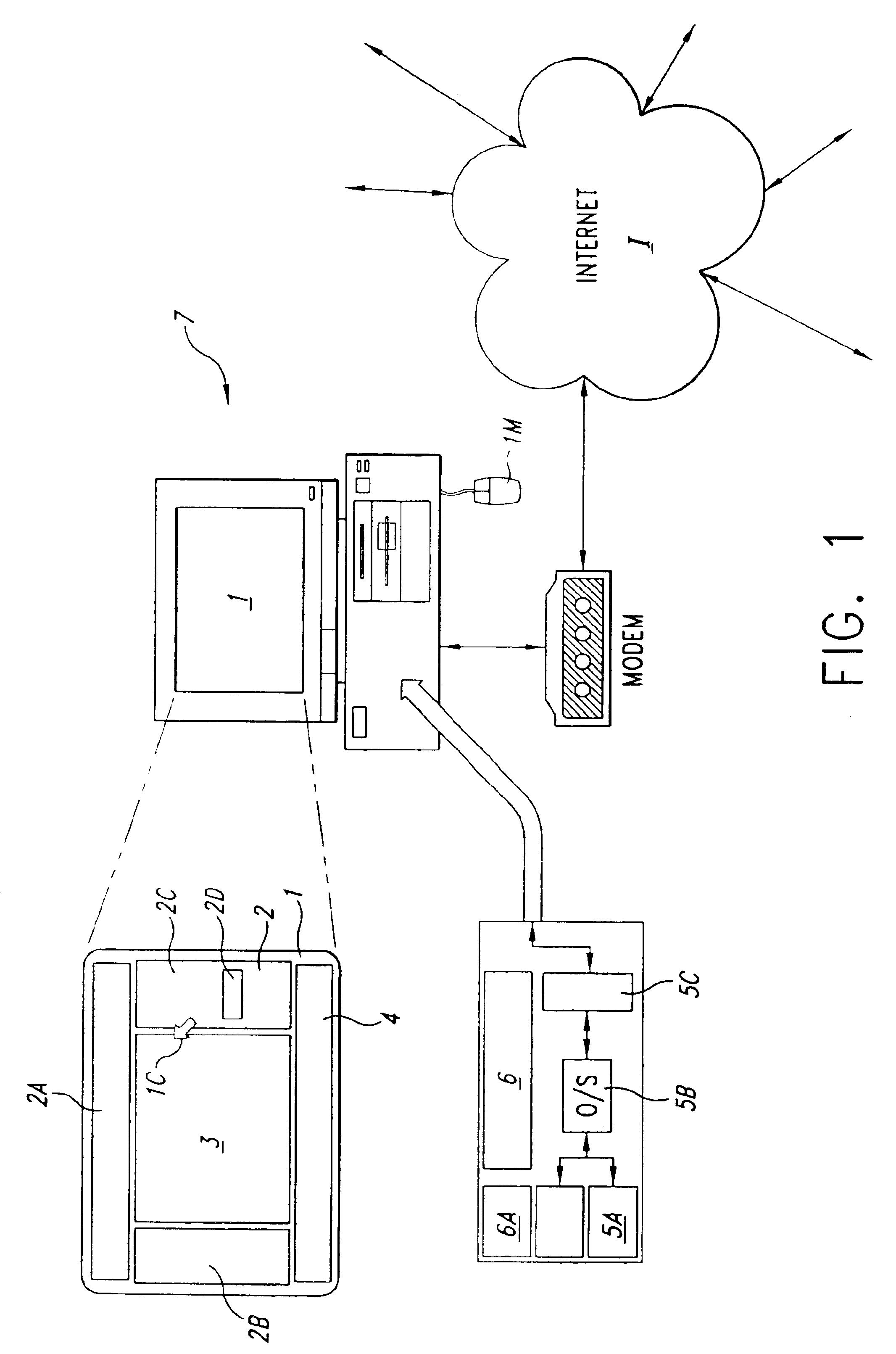
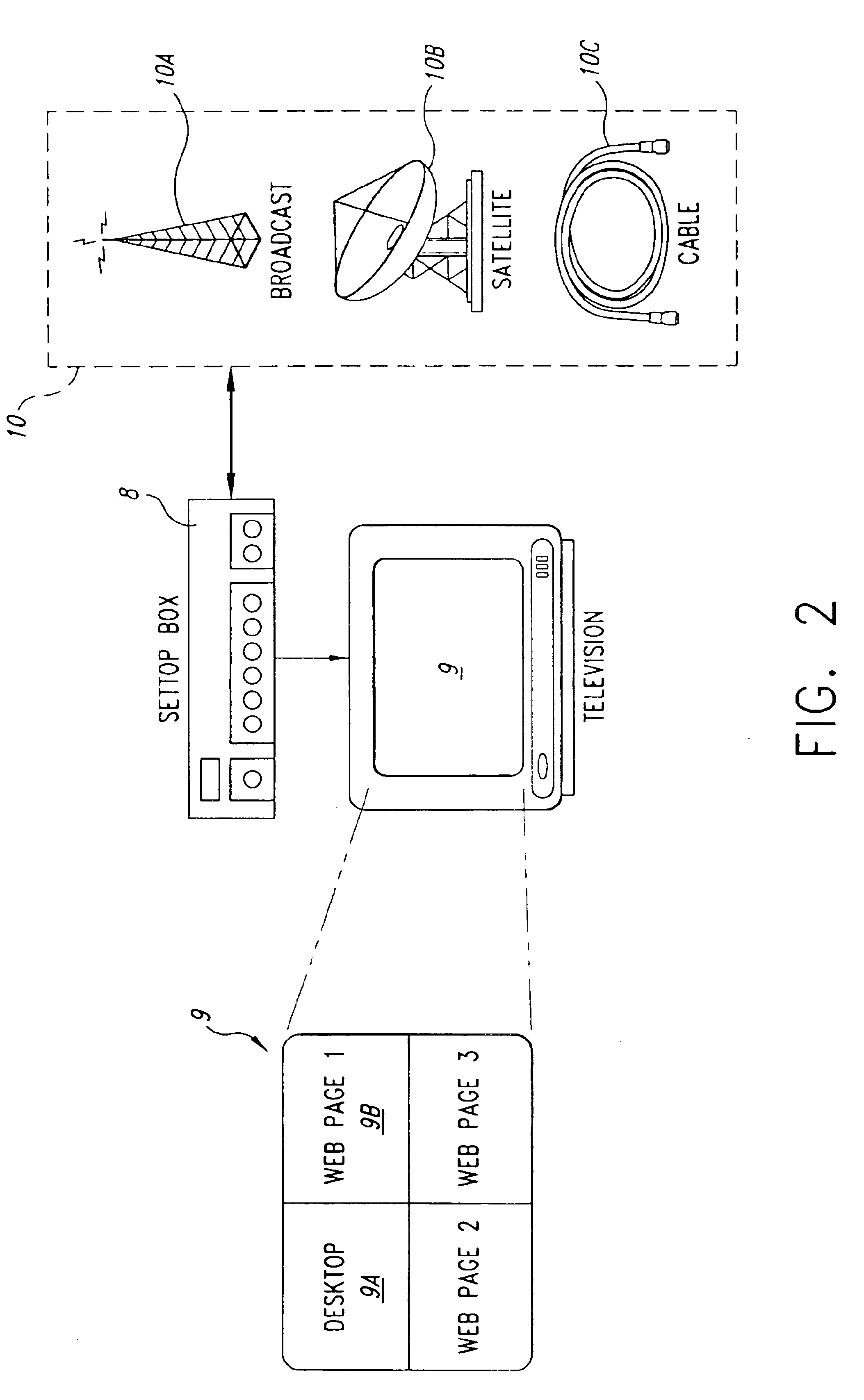
CROSS-REFERENCE TO RELATED APPLICATIONS[0001]This application is a continuation-in-part of U.S. patent application Ser. No. 09 / 666,032, filed on Sep. 20, 2000, now issued as U.S. Pat. No. 6,630,943 B1 on Oct. 7, 2003 and claims the benefit of U.S. Provisional Application No. 60 / 183,453, filed on Feb. 18, 2000 and 60 / 248,438 filed on Nov. 13, 2000.TECHNICAL FIELD[0002]The present invention relates to a method and system for controlling the display of information on a display surface and, in particular, to computer software that displays one or more user interfaces that can coexist with a native user interface provided by the computer system.BRIEF DESCRIPTION OF THE DRAWINGS[0003]FIG. 1 is a block diagram of a first embodiment of the present invention.[0004]FIG. 2 is a block diagram of a second embodiment of the present invention.[0005]FIG. 3 is a diagram of a standard display with an overscan user interface on all four borders of the display.[0006]FIG. 4 is a block diagram of the bas...

Claims


Application Information

Patent Timeline
IPC IPC(8): G09G5/14G06F3/033G06F3/14G06F9/44G09G1/16G06F3/038
CPCG06F3/038G06F3/0481G06F3/14G06F9/4443G09G5/14G09G1/167G06F2203/04802Y10S715/972G09G2310/0232G09G2370/027Y10S715/967G06F9/451
Inventor NASON, D. DAVIDSYEDACH, VOLODYMYRKENNEDY, JOHN R.
Owner OSTENDO TECH INC
Learn More