Eureka AIR delivers breakthrough ideas for toughest innovation challenges, trusted by R&D personnel around the world.

Physiological monitoring devices with adjustable signal analysis and interrogation power and monitoring methods using same

a physiological monitoring and signal analysis technology, applied in the field of monitoring devices, can solve the problems of reducing the accuracy of metrics derived from ppg data, swamping out time-varying changes in photon intensity, and difficult to ascertain signals of interest, so as to increase reduce the brightness of the user interface, and increase the subject's stress level

Active Publication Date: 2017-01-10
YUKKA MAGIC LLC
View PDF478 Cites 74 Cited by
  • Summary
  • Abstract
  • Description
  • Claims
  • Application Information

AI Technical Summary

Benefits of technology

[0027]In some embodiments, the sensor is in communication with a user interface. In some embodiments, the processor may be configured to increase user interface brightness and / or font size of alphanumeric characters displayed on the user interface in response to detecting an increase in subject stress level, and is configured to decrease user interface brightness and / or font size of alphanumeric characters displayed on the user interface in response to detecting a decrease in subject stress level. In some embodiments, the processor may be configured to enlarge an image displayed within the user interface and / or make an image displayed within the user interface easier to view / comprehend (e.g., increase the resolution of the image, etc.) in response to detecting an increase in subject stress level. The processor may be configured to decrease an image displayed within the user interface and / or reduce the resolution of an image displayed within the user interface in response to detecting an increase in subject stress level.
[0029]In some embodiments, the sensor comprises a voice recognition system, and the method includes increasing processing power for the voice recognition system in response to detecting an increase in subject stress level, and decreasing processing power for the voice recognition system in response to detecting a decrease in subject stress level.
[0030]In some embodiments, the sensor is in communication with a user interface, and the method includes increasing user interface brightness and / or font size of alphanumeric characters displayed on the user interface in response to detecting an increase in subject stress level, and decreasing user interface brightness and / or font size of alphanumeric characters displayed on the user interface in response to detecting a decrease in subject stress level.
[0032]Monitoring devices, according to embodiments of the present invention, are advantageous over conventional monitoring devices because, by changing signal analysis frequency and / or sensor interrogation power, power savings may be incurred. Moreover, increasing sensing power or sampling frequency may allow for finer, more accurate sensor data to be collected during periods of rapid body activity, e.g., during exercising, running, walking, etc. Conversely sensor data changes during periods of inactivity maybe infrequent and require significantly lower power to achieve sufficient data resolution to accurately describe physiological changes.

Problems solved by technology

If the incidental and scattered photon count magnitude changes due to light coupling variation between the source or detector and the skin or other body tissue, then the signal of interest can be difficult to ascertain due to large photon count variability caused by motion artifacts.
Physical activity, such a walking, cycling, running, etc., may cause motion artifacts in the optical scatter signal from the body, and time-varying changes in photon intensity due to motion artifacts may swamp-out time-varying changes in photon intensity due to blood flow changes.
This can result in a much lower accuracy in metrics derived from PPG data, such as heart rate and breathing rate.
Unfortunately, incorporation of a photoplethysmograph device into an earphone poses several challenges.
For example, earphones may be uncomfortable to wear for long periods of time, particularly if they deform the ear surface.
Moreover, human ear anatomy may vary significantly from person to person, so finding an earbud form that will fit comfortably in many ears may pose significant challenges.
Although, these features may facilitate retention of an earbud within an ear during high acceleration and impact modalities, they may not adequately address optical skin coupling requirements needed to achieve quality photoplethysmography.
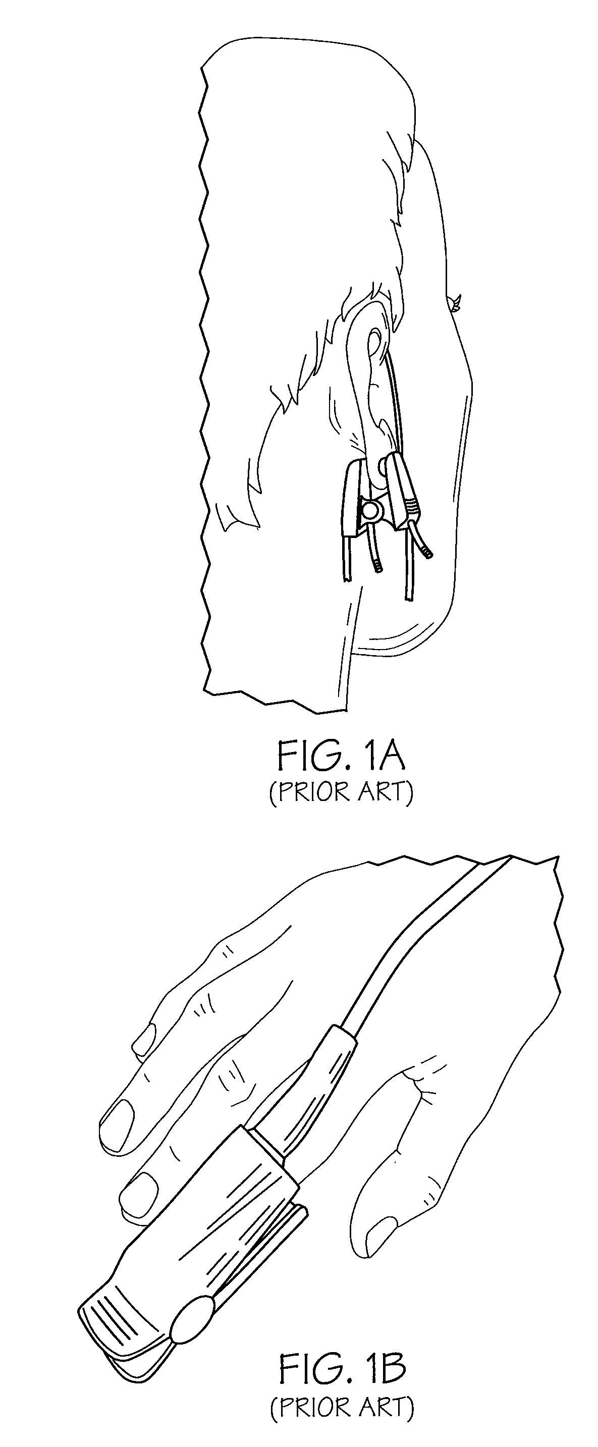
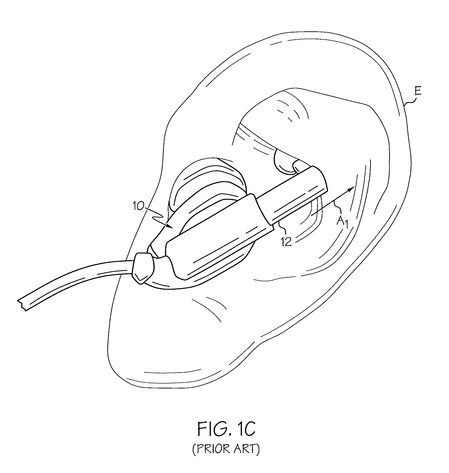
Conventional photoplethysmography devices, as illustrated for example in FIGS. 1A-1C, typically suffer from reduced skin coupling as a result of subject motion.
Unfortunately, these conventional devices tend to have a large mass and may not maintain consistent skin contact when subjected to large accelerations, such as when a subject is exercising.
However, there are several drawbacks to the device 10 of FIG. 1C.
In addition, because the earbud 10 is held in place with one primary spring force direction, significant discomfort can be experienced by the end user.
Because PPG used in wearable devices employs an optical technology, requiring the powering of optical emitters and microprocessors via a wearable battery, managing power consumption can be challenging.
Thus, employing a high-power algorithm during exercise may have the benefit of accurately monitoring heart rate during exercise but may also have the unwanted effect of draining the battery of the wearable device such that the device will not have enough power to measure a subject over the course of a day or week during non-exercising periods.
Conversely sensor data changes during periods of inactivity maybe infrequent and require significantly lower power to achieve sufficient data resolution to accurately describe physiological changes.

Method used


Image

  • Physiological monitoring devices with adjustable signal analysis and interrogation power and monitoring methods using same
  • Physiological monitoring devices with adjustable signal analysis and interrogation power and monitoring methods using same
  • Physiological monitoring devices with adjustable signal analysis and interrogation power and monitoring methods using same

Examples


Embodiment Construction

[0046]The present invention will now be described more fully hereinafter with reference to the accompanying figures, in which embodiments of the invention are shown. This invention may, however, be embodied in many different forms and should not be construed as limited to the embodiments set forth herein. Like numbers refer to like elements throughout. In the figures, certain layers, components or features may be exaggerated for clarity, and broken lines illustrate optional features or operations unless specified otherwise. In addition, the sequence of operations (or steps) is not limited to the order presented in the figures and / or claims unless specifically indicated otherwise. Features described with respect to one figure or embodiment can be associated with another embodiment or figure although not specifically described or shown as such.

[0047]It will be understood that when a feature or element is referred to as being “on” another feature or element, it can be directly on the o...


PUM


Abstract

A monitoring device configured to be attached to a body of a subject includes a sensor configured to detect and / or measure physiological information from the subject, and a processor coupled to the sensor that is configured to receive and analyze signals produced by the sensor. The processor is configured to change signal analysis frequency and / or sensor interrogation power in response to detecting a change in subject activity, a change in subject stress level, a change in environmental conditions, a change in time, and / or a change in location of the subject.

Description

RELATED APPLICATIONS[0001]This application claims the benefit of and priority to U.S. Provisional Patent Application No. 62 / 030,951 filed Jul. 30, 2014, and U.S. Provisional Patent Application No. 62 / 109,196 filed Jan. 29, 2015, the disclosures of which are incorporated herein by reference as if set forth in their entireties.FIELD OF THE INVENTION[0002]The present invention relates generally to monitoring devices and, more particularly, to monitoring devices for measuring physiological information.BACKGROUND OF THE INVENTION[0003]Photoplethysmography (PPG) is based upon shining light into the human body and measuring how the scattered light intensity changes with each pulse of blood flow. The scattered light intensity will change in time with respect to changes in blood flow or blood opacity associated with heart beats, breaths, blood oxygen level (SpO2), and the like. Such a sensing methodology may require the magnitude of light energy reaching the volume of flesh being interrogate...

Claims


Application Information

Patent Timeline
Patent Type & Authority Patents(United States)
IPC IPC(8): A61B5/01A61B5/021A61B5/00A61B5/1455A61B5/16G05B19/048A61B5/024A61B5/0205A61B5/11A61B5/08
CPCA61B5/0205A61B5/0059A61B5/01A61B5/021A61B5/02055A61B5/02416A61B5/02427A61B5/1118A61B5/1123A61B5/14551A61B5/14552A61B5/165A61B5/443A61B5/4809A61B5/68A61B5/6815A61B5/6816A61B5/6826A61B5/72A61B5/7207G05B19/048A61B2560/0266G05B2219/2652A61B5/02405A61B5/0816A61B2503/10A61B2560/0242A61B5/024A61B5/4266A61B5/6803A61B5/7203A61B5/7271A61B5/742A61B5/6831A61B2560/0247A61B5/7282A61B2560/0209
Inventor LEBOEUF, STEVEN FRANCISTUCKER, JESSE BERKLEYAUMER, MICHAEL EDWARDJUST, STEVEN MATTHEWFELICE, MARK ANDREW
Owner YUKKA MAGIC LLC
Why Eureka
Eureka Blog
Learn More