Inter-region thermal complementary system by distributed cryogenic and thermal devices

a cryogenic and thermal device technology, applied in the direction of lighting and heating apparatus, domestic cooling apparatus, heating types, etc., can solve the problems of difficult utilization, difficult to achieve, and difficulty in effective utilization of returning pipes, so as to achieve the thermal balance of each main helical loop

Inactive Publication Date: 2005-05-10
MAYEKAWA MFG CO LTD
View PDF8 Cites 2 Cited by
  • Summary
  • Abstract
  • Description
  • Claims
  • Application Information

AI Technical Summary

Benefits of technology

[0051]The constitution like this is advantageous in the point of view of heat transfer. For example, cryogenic heat (lower temperature water) can be transferred from the main helical loop which is provided in a region where electric power generation plants and industrial complexes, etc. are located and has ample cryogenic source to the main helical loop provided in a commercial district where cryogenic source is insufficient via the main helical loop provided in an intermediate industrial district, by utilizing the heat conversion function of the energy modulation sections provided between each main helical loop, and thermal balance of each main helical loop can be achieved.

Problems solved by technology

However, in most cases the excess in heat source systems is dissipated into the atmosphere in prior arts.
The excess heat in heat source systems used on citizen level such as distributed small scale co-generation apparatuses is difficult to be utilized, so the excess heat is discarded without utilized if there is no system for recovering and reusing the excess heat, and this promotes heat island phenomenon.
Heat insulation of the pipes was necessary and effective utilization of the returning pipes was a problem.
Therefore, the area to be supplied with heat surrounded by the looped endless water channel is restricted.

Method used


Image

  • Inter-region thermal complementary system by distributed cryogenic and thermal devices
  • Inter-region thermal complementary system by distributed cryogenic and thermal devices
  • Inter-region thermal complementary system by distributed cryogenic and thermal devices

Examples


Embodiment Construction

[0067]A preferred embodiment of the present invention will now be detailed with reference to the accompanying drawings. It is intended, however, that unless particularly specified, dimensions, materials, relative positions and so forth of the constituent parts in the embodiments shall be interpreted as illustrative only not as limitative of the scope of the present invention.

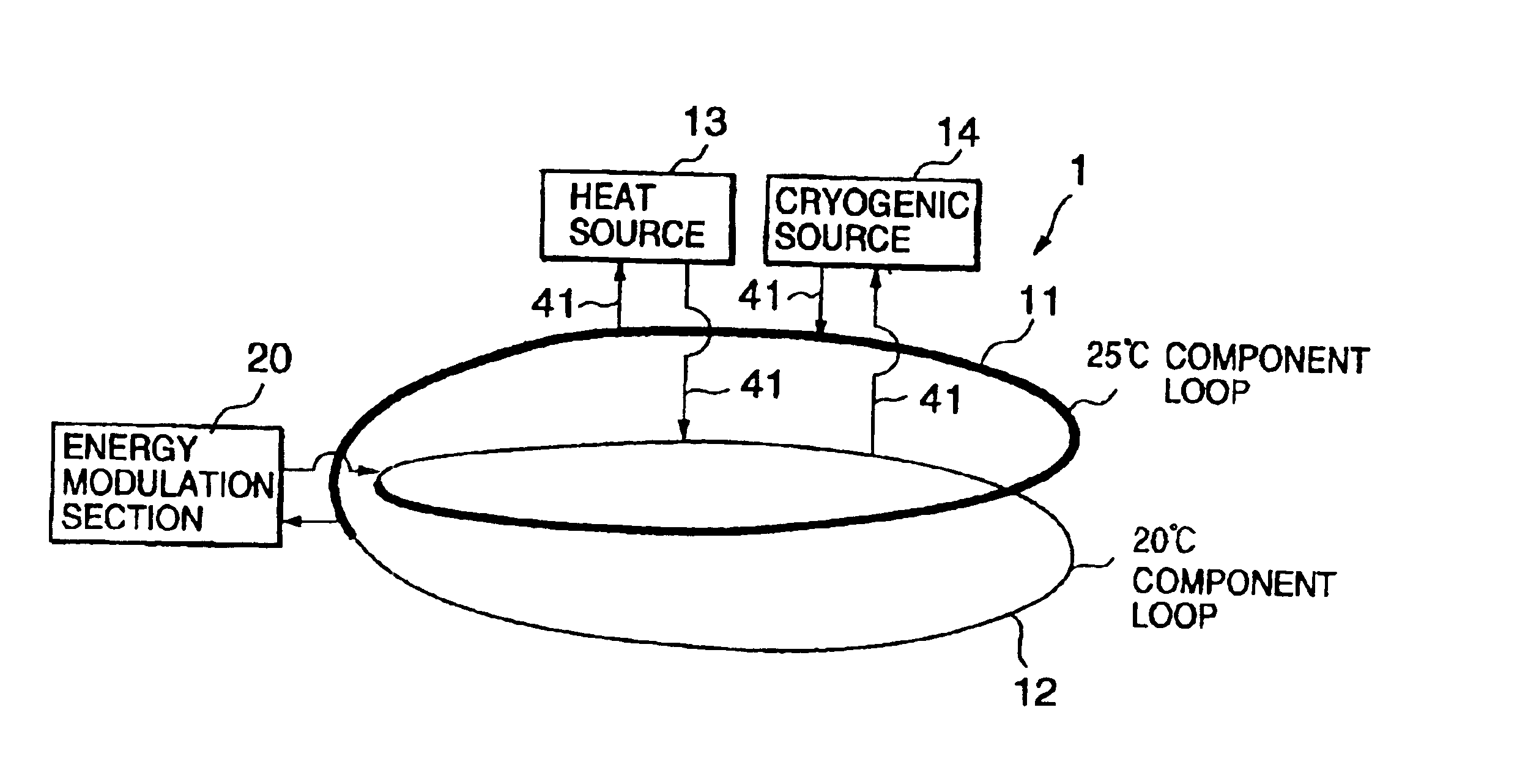
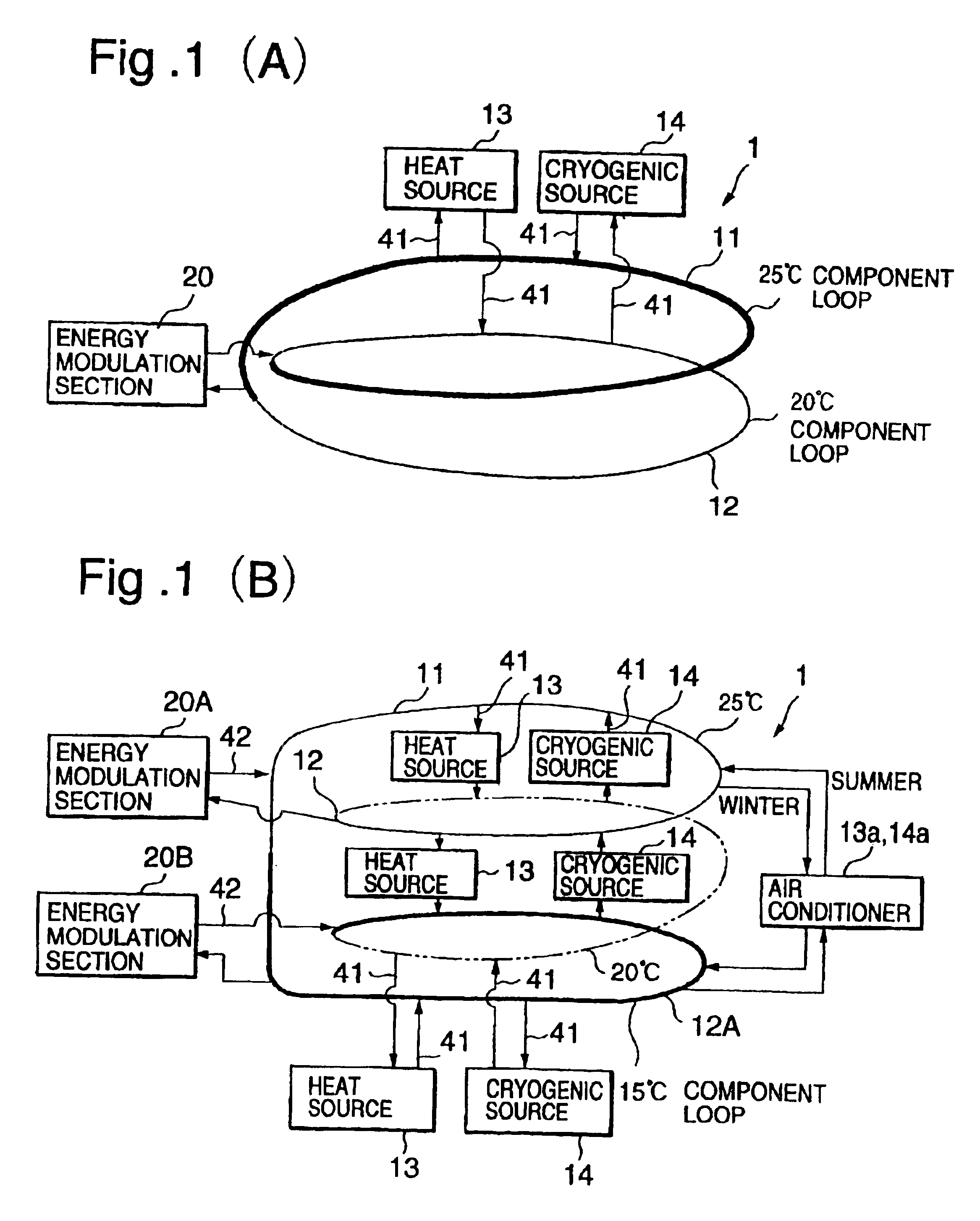
[0068]FIG. 1 is a basic block diagram of the inter-region thermal complementary system according to the present invention. A duplex helical loop (pipe)1 is buried under the surface of roads and grounds of housing, commercial or industrial complexes the duplex helical loop being formed by turning a pipe in two turns in an endless duplex loop and water being filled in it. In FIG. 1(A), distributed refrigerating apparatuses (distributed cryogenic source) 14 and distributed heat source apparatuses 13 (distributed heat source) are connected to the loop so that the water on the lower loop 12 is kept to a relatively lo...


PUM


Abstract

The object of the invention is to provide a thermal complementary (combination of heat supply and heat discharge) system which can complement heat without the restriction of area of a region to be supplied with heat. An endless multiplex helical loop is formed to complement the heat produced in a region such as plants and regional facilities on a reciprocal basis, and the water is not circulated forcibly but achieves heat transfer in the helical loop.
Liquid or slurry-like water is sealed in the annular endless channel (endless loop) without forcibly circulated. Therefore, loop diameter of the annular endless channel, that means the area of the region, is not limited. The water forms temperature zones in the endless helical loop, the temperature being different per each component loop. Distributed cryogenic sources and thermal sources are thermally connected to said multiplex helical loop so that heat (i.e. water) can be taken in or discharged to or from said cryogenic or thermal sources. As the water needs not be forcibly circulated, the power for forcibly circulating the water is eliminated resulting in reduced running cost. Refrigerating apparatuses, heat source apparatuses, etc. distributed in the region are effectively utilized and also central control of energy supply through the multiplex helical loops is made possible.

Description

FIELD OF THE INVENTION[0001]The present invention relates to an inter-region thermal complementary system aiming the recovery and reuse of the heat emitted from plants and distributed cryogenic and thermal devices in a region, specifically to an inter-region thermal complementary system capable of complementing heat by forming an endless loop filled with water or slurry as heat source and heat sink.TECHNICAL BACKGROUND[0002]Energy policy has been under review on every level such as municipalities, corporations, and civilians in the viewpoint of preventing global warming.[0003]In the field of electric energy, it has been proposed to eliminate the loss in electric power transmission and to raise energy efficiency by effectively utilizing waste heat by shifting from a large scale, which is centralized power plant system to a small scale electric power source dispersed in the region.[0004]On the other hand, there are energy-saving technologies conducted by corporations such as co-genera...

Claims


Application Information

Patent Timeline
Patent Type & Authority Patents(United States)
IPC IPC(8): F25D17/02F25D17/00
CPCF25D17/02F24F2005/0039
Inventor SANO, MAKOTOKAWAMURA, KUNIAKIMATSUDA, JUNJIFUJIMA, KATSUMIKUDO, TAKANORIKAWAZU, YOUICHIYOSHIKAWA, CHOIKUFUKANO, SYUJI
Owner MAYEKAWA MFG CO LTD
Why Eureka
Try Eureka