
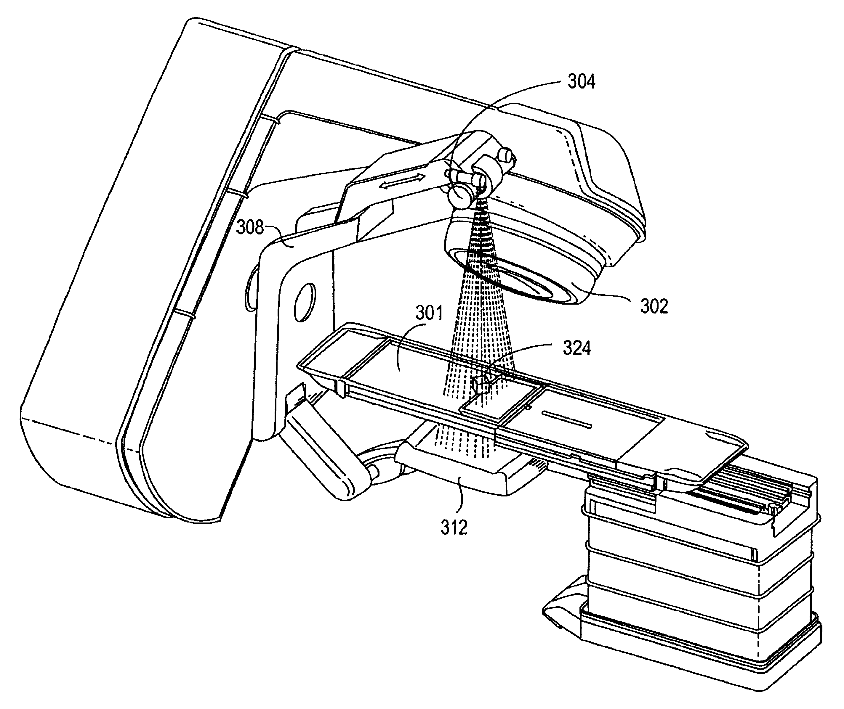
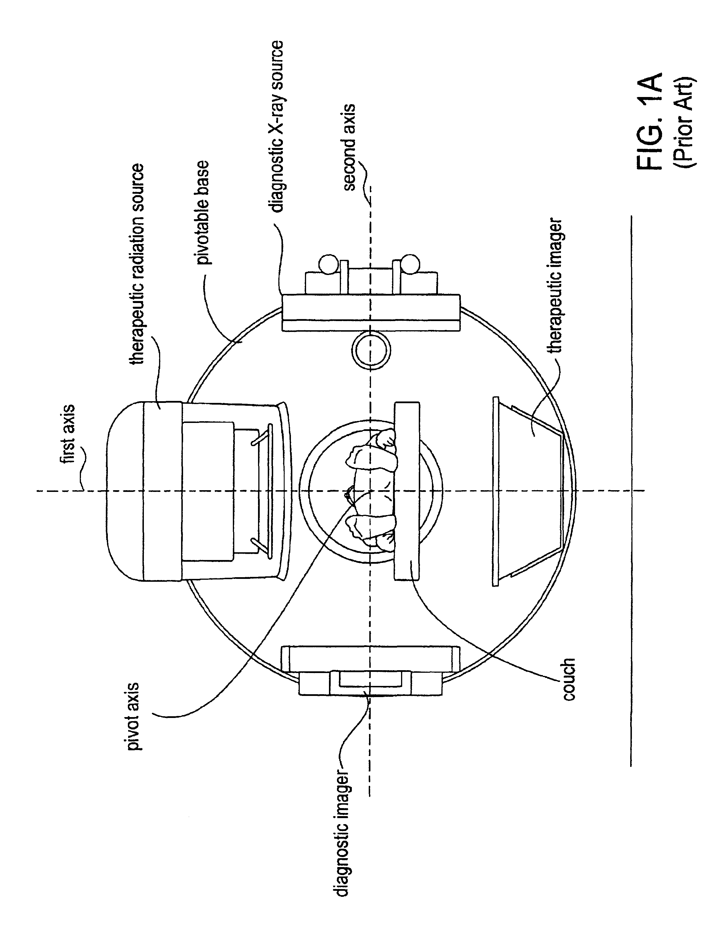
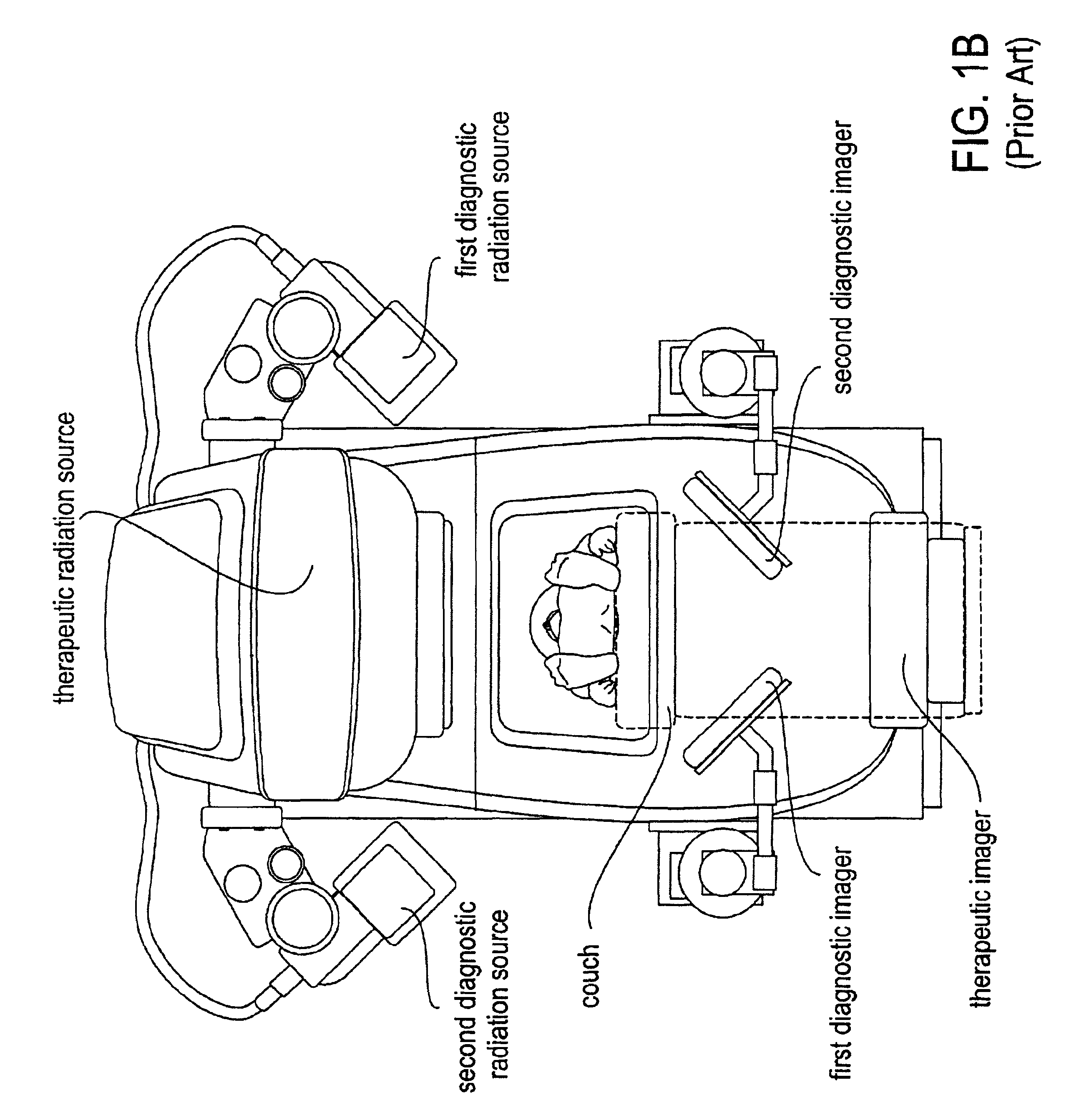
Radiotherapy apparatus equipped with an articulable gantry for positioning an imaging unit

a radiotherapy apparatus and positioning technology, applied in radiation therapy, medical science, radiation therapy, etc., can solve the problems of low contrast, insufficient quality, limited space for the various components,

Inactive Publication Date: 2005-05-03
VARIAN MEDICAL SYSTEMS
View PDF55 Cites 355 Cited by
  • Summary
  • Abstract
  • Description
  • Claims
  • Application Information

AI Technical Summary

Benefits of technology

[0010]This arrangement for positioning the multiple-energy imaging unit to be in line with either one of the radiation sources can provide improved imaging useful in directing the treatment beams used in radiation therapy. A first energy level in the kV range can radiate a target volume to provide diagnostic quality image information from the multiple-energy imaging unit. The diagnostic information can be used to better direct radiation at a second energy level in the MV range for therapeutic radiation of the target volume and from which verification information from the multiple-energy imaging unit can then be acquired. The second gantry can pivot, extend / retract, and / or articulate to receive diagnostic radiation or therapeutic radiation. The application of therapeutic radiation and diagnostic radiation can alternate in any combination to provide diagnostic imaging and verification imaging as a result of the degrees of freedom available to position the single multiple-energy imaging unit.

Problems solved by technology

One of the challenges inherent in radiotherapy treatment is the accurate positioning of the tumor in the radiation field.
However, these methods at target location deliver images of low contrast and insufficient quality.
These problems associated with utilizing high energy X-rays produced by a megavolt electron beam are the result of interacting with matter mostly due to Compton scattering, in which the probability of interactions is proportional to the electron density.
This leaves a quite limited amount of space for the various components such as the radiation shielding in the radiation head, and particularly for the magnet system.
To a significant extent, the design challenge over the years has been to stay within this space, to reduce cost where possible, and while making major advances in the clinical utility of machines.

Method used


Image

  • Radiotherapy apparatus equipped with an articulable gantry for positioning an imaging unit
  • Radiotherapy apparatus equipped with an articulable gantry for positioning an imaging unit
  • Radiotherapy apparatus equipped with an articulable gantry for positioning an imaging unit

Examples


Embodiment Construction

[0022]A method and apparatus for a radiotherapy clinical treatment machine for positioning an imager to oppose one or more radiation sources is disclosed. For purposes of discussing the invention, it is to be understood that various terms are used by those knowledgeable in the art to describe apparatus, techniques, and approaches.

[0023]In the following description, for purposes of explanation, numerous specific details are set forth in order to provide a thorough understanding of the present invention. It will be evident, however, to one skilled in the art that the present invention may be practiced without these specific details. In some instances, well-known structures and devices are shown in gross form rather than in detail in order to avoid obscuring the present invention. These embodiments are described in sufficient detail to enable those skilled in the art to practice the invention, and it is to be understood that other embodiments may be utilized and that logical, mechanica...


PUM


Abstract

An apparatus including a first radiation source attached to a first gantry, at least one second radiation source, a second gantry that is rotatable; and an imager attached to an articulable end of the second gantry.

Description

FIELD OF THE INVENTION[0001]The present invention pertains in general to oncology radiation therapy. In particular, the invention involves an X-ray and electron radiotherapy machine used in radiation treatment applications.BACKGROUND OF THE INVENTION[0002]The use of linear accelerators for the generation of either electron radiation or X-ray radiation is well known. After generating a stream of electrons, components in the radiotherapy machine can convert the electrons to X-rays, a flattening filter can broaden the X-ray beam, the beam can be shaped with a multileaf collimator, and a dose chamber can be arranged at the exit of an accelerator. A detector is mounted and is mechanically or electronically scanned synchronously with the mechanically or electronically scanned paraxial X-ray beam, providing continuous monitoring of alignment of the patient's anatomy. These systems typically provide either static fixed field radiation therapy or fully dynamic intensity modulated radiation t...

Claims


Application Information

Patent Timeline
IPC IPC(8): A61N5/10
CPCA61N5/1049A61N2005/1061A61N2005/1054
Inventor GRAF, ULRICH MARTIN
Owner VARIAN MEDICAL SYSTEMS
Learn More