Amplitude limiting apparatus and multi-carrier signal generating apparatus

Inactive Publication Date: 2005-05-03
KOKUSA ELECTRIC CO LTD
View PDF15 Cites 10 Cited by
  • Summary
  • Abstract
  • Description
  • Claims
  • Application Information

AI Technical Summary

Benefits of technology

[0013]An object of the present invention, in view of the background circumstances stated above, is to provide an amplitude limiting apparatus capable of effectively suppressing the peak level of the amplitude of transmission signals in a multi-carrier communication system or the like.[Amplitude Limiting Apparatus]

Problems solved by technology

As such, a high peak in the amplitude of transmission signals would fall on a nonlinear part of the amplification characteristics of the power amplifier 126 (FIG. 1) and be amplified in power, which would cause the trouble that transmission signals supplied by the power amplifier 126 are distorted and give rise to spurious signals.
However, this solution would entail not only a large power amplifier 126 but also greater power consumption and heat generation, inevitably increasing the size and price of the whole OFDM transmitter 1.
However, merely limiting the amplitude of transmission signals would give rise to many distortions in transmission signals due to the suppression of the amplitude itself.
Therefore, merely limiting the amplitude of transmission signals would not be an appropriate solution to this trouble.

Method used


Image

  • Amplitude limiting apparatus and multi-carrier signal generating apparatus
  • Amplitude limiting apparatus and multi-carrier signal generating apparatus
  • Amplitude limiting apparatus and multi-carrier signal generating apparatus

Examples


modification 1

[Modification 1]

[0134]A first modification of the OFDM transmitter according to the invention will be described below.

[0135]FIG. 13 illustrates the configuration of a third OFDM transmitter 3 according to the invention.

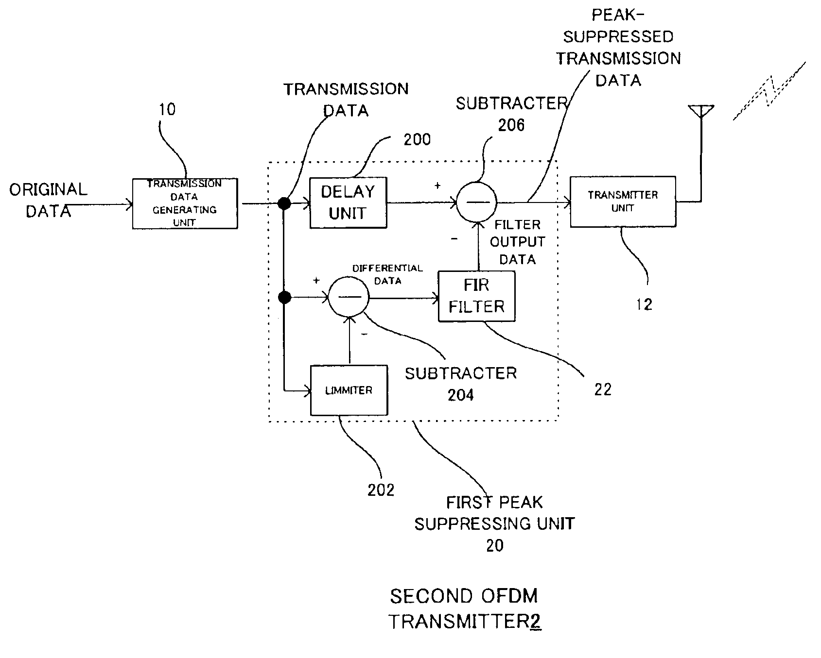
[0136]As shown in FIG. 13, the third OFDM transmitter 3 has a configuration in which the first peak suppressing unit 20 in the second OFDM transmitter 2 (FIG. 5 and elsewhere) is replaced with a second peak suppressing unit 24.

[0137]The second peak suppressing unit 24 has a configuration in which the FIR filter unit 22 is replaced with a plurality of FIR filter units 22-1 through 22-k (k is an integer of not smaller than 2; FIG. 13 shows the case of k=2), and a switching unit 208 and a level determination unit 210 are added.

[0138]Of the constituent parts of the OFDM transmitter 3 shown in FIG. 13, those substantially the same as their counterparts in the OFDM transmitters 1 and 2 respectively shown in FIG. 1 and FIG. 5 are denoted by respectively the same reference si...

modification 2

[Modification 2]

[0145]A second modification of the OFDM transmitter according to the invention will be described below.

[0146]FIG. 14 illustrates the configuration of a fourth OFDM transmitter 4 according to the invention.

[0147]As shown in FIG. 14, the fourth OFDM transmitter 4 has a configuration in which the second OFDM transmitter 2 (FIG. 5 and elsewhere) is provided with a plurality of first peak suppressing units 20-1 through 20-k (FIG. 14 shows a case of k=2).

[0148]Of the constituent parts of the OFDM transmitter 4 shown in FIG. 14, those substantially the same as their counterparts in the OFDM transmitters 1 through 3 shown in FIG. 1, FIG. 5, FIG. 13 and elsewhere are denoted by respectively the same reference signs.

[0149]Noted that, in the OFDM transmitter 4, the FIR filter units 22 (not shown in FIG. 14; instead see FIG. 5, FIG. 8 and elsewhere) contained in the peak suppressing units 20-1 and 20-2 have different subcarrier bands as their pass bands.

[0150]Further, the FIR fi...

second embodiment

[Second Embodiment]

[0160]A second preferred embodiment of the present invention will be described below.

[0161]The second and third OFDM transmitters 2 and 3 (FIG. 5 and FIG. 13) described as the first preferred embodiment of the invention suppress any peak arising in transmission data by attenuating only one specific subcarrier.

[0162]Unlike that, a fifth OFDM transmitter 5 (to be described afterwards with reference to FIG. 20 and other drawings), which is the second preferred embodiment of the invention, suppresses any peak arising in transmission data by attenuating a plurality of subcarriers.

[0163][Outline of OFDM Transmitter 5]

[0164]First, the manner in which the OFDM transmitter 5 carries out peak suppression will be described.

[0165]The following description will be illustrated by a case in which transmission data contains 16 subcarriers.

[0166]FIG. 16 shows examples of peaks that may arise where transmission data contains 16 subcarriers.

[0167]As shown in FIG. 16, even where tran...


PUM


Abstract

A peak level of amplitude of transmission signals in a multi-carrier communication system or the like is to be effectively suppressed. A transmission data generating unit generates digital transmission data from original data by an OFDM system. A limiter of a peak suppressing unit limits a level of transmission data using thresholds. A subtractor subtracts output data of the limiter from the transmission data to generate differential data. A subtractor suppresses the peak level by subtracting the differential data from transmission data whose timing is coordinated by delay units. A transmitter unit converts the transmission data whose peak level is suppressed into analog transmission signals, further converts their frequency, amplifies their power, and transmits the frequency-converted and power-amplified signals to a radio line via an antenna.

Description

BACKGROUND OF THE INVENTION[0001]1. Field of the Invention[0002]The present invention relates to an amplitude limiting apparatus for limiting the amplitude of signals.[0003]2. Description of the Related Art[0004]For instance, Patent Reference 1 discloses an orthogonal frequency division multiplex (OFDM) system as a multi-carrier communication system for transmitting data by use of multiple carriers.[0005]Patent References 2 through 7 disclose methods by which the peak level of transmission signals in a multi-carrier communication system or the like is suppressed in order to reduce nonlinear distortions, occurring from their amplification, in nonlinear portions of the amplification characteristics of the power amplifier.[0006][Patent Reference 1] Nikkei Electronics (Apr. 8, 2002, pp. 102 to 127) (in Japanese)[0007][Patent Reference 2] Japanese published unexamined patent application 2001-339361[0008][Patent Reference 3] Japanese published unexamined patent application 2002-44052[0009...

Claims


Application Information

Patent Timeline
IPC IPC(8): H03G11/00H04L27/26
CPCH04L27/2624H03G11/008
Inventor NAITO, MASASHI
Owner KOKUSA ELECTRIC CO LTD
Why Eureka
Try Eureka