
Altering operating frequency and voltage set point of a circuit in response to the operating temperature and instantaneous operating voltage of the circuit

a technology of operating frequency and voltage set point, applied in the field of control, can solve the problems of large amount of available performance, device ceases to operate correctly, and may even suffer permanent damag

Inactive Publication Date: 2005-04-26
SONY CORP OF AMERICA
View PDF36 Cites 69 Cited by
  • Summary
  • Abstract
  • Description
  • Claims
  • Application Information

AI Technical Summary

Problems solved by technology

The chip can be subjected to a range of temperatures below a maximum temperature (Tjmax) at which the device ceases to operate correctly or may even suffer permanent damage.
Thus, because the prior art has limited the operating frequency based upon a worst corner case assumption about voltage and temperature, and because these conditions will not typically be present (individually, much less in combination), the prior art leaves a great deal of available performance on the table.

Method used


Image

  • Altering operating frequency and voltage set point of a circuit in response to the operating temperature and instantaneous operating voltage of the circuit
  • Altering operating frequency and voltage set point of a circuit in response to the operating temperature and instantaneous operating voltage of the circuit
  • Altering operating frequency and voltage set point of a circuit in response to the operating temperature and instantaneous operating voltage of the circuit

Examples


Embodiment Construction

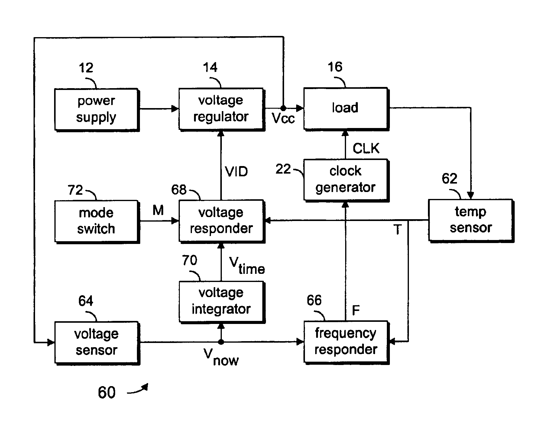
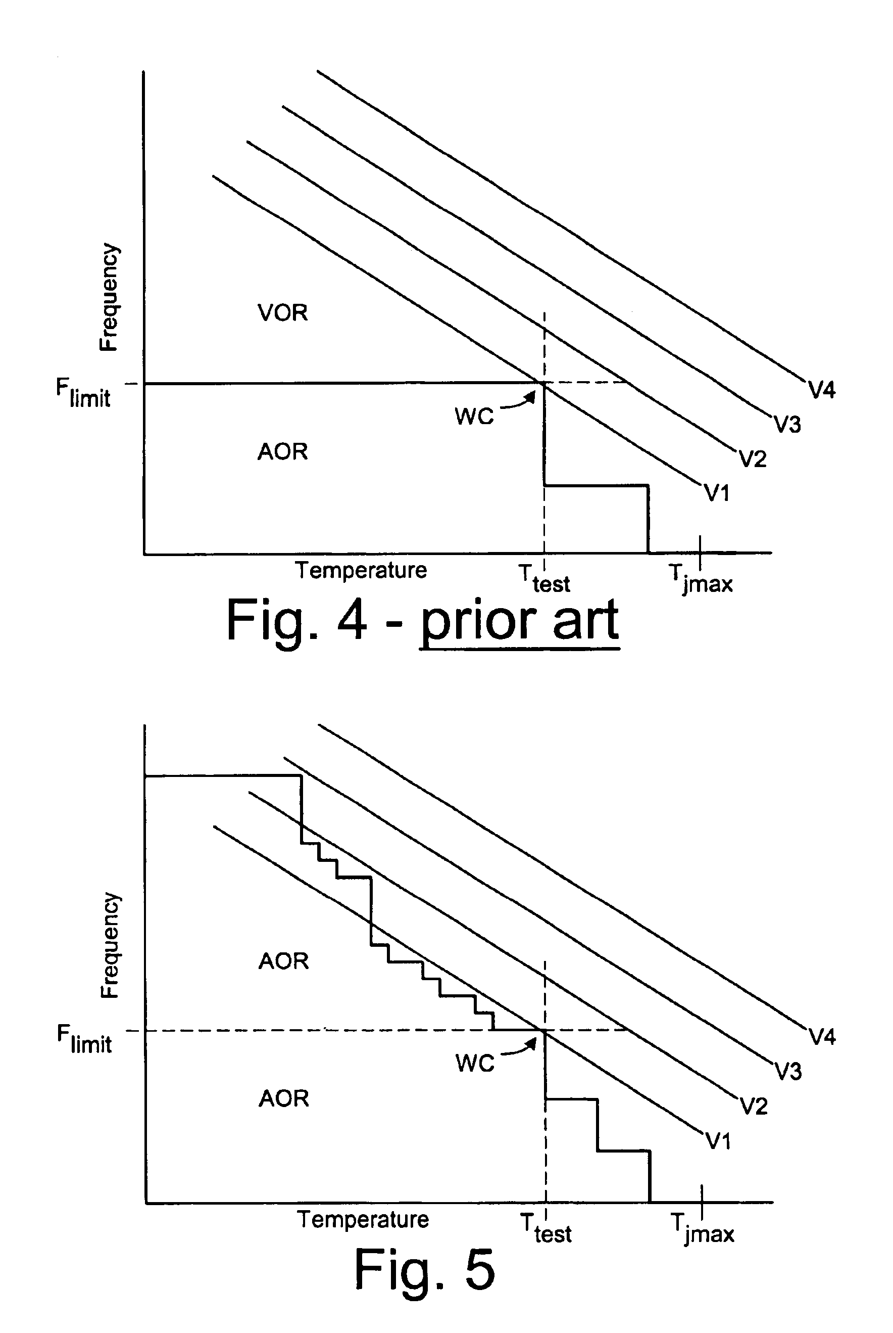
[0019]FIG. 5 illustrates one mode of operation of the invention. At the worst corner case of minimum voltage V1 and maximum temperature Ttest, the chip will be clocked at frequency Flimit, just as in the prior art. However, as the temperature falls below Ttest, the operating frequency is not fixed at Flimit, but can be raised, so long as it does not exceed the limit imposed by the voltage / temperature combination. This may be done in a series of steps, such as via a lookup table which uses temperature and voltage as addressing or index values and which outputs frequency values. In other embodiments, it may be done using an analog delay element which relies on the same physical properties as the load circuit.

[0020]The actual operating range (AOR) is extended to include the area above the Flimit frequency at which the prior art is limited. Under some circumstances, the system may elect to raise the operating voltage, such as from V1 to V2. This, in turn, will generally permit the frequ...


PUM


Abstract

Setting the clock frequency provided to a load circuit as function of the operating temperature and supply voltage of the load circuit, and setting the supply voltage as a function of the operating temperature of the load circuit. The load circuit can be safely operated above the frequency which would be the limit if the load circuit were operating at the maximum test temperature. At the given operating temperature, the supply voltage can be raised to permit even higher frequency operation, or lowered to reduce power.

Description

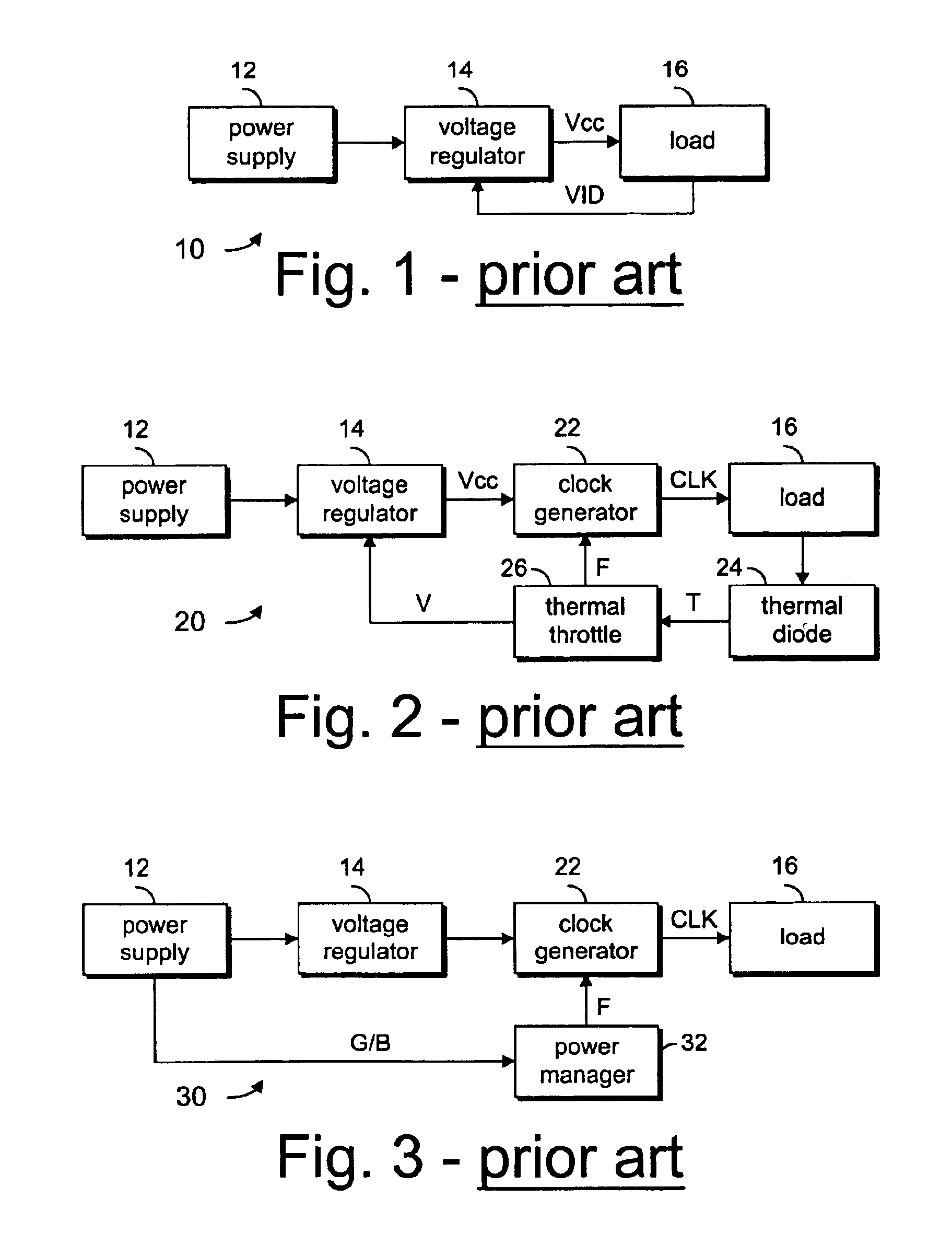
[0001]This application is related to application Ser. No. 10 / 136,390 titled CLOCK GENERATING CIRCUIT AND METHOD, filed May 2, 2002; application Ser. No. 10 / 136,318 titled VOLTAGE CONTROL FOR CLOCK GENERATING METHOD, filed May 2, 2002; application Ser. No 10 / 136,474 titled FREQUENCY CONTROL FOR CLOCK GENERATING CIRCUIT, filed May 2, 2002; and application Ser. No. 10 / 136,321 titled VOLTAGE ID BASED FREQUENCY CONTROL FOR CLOCK GENERATING CIRCUIT, filed May 2, 2002.BACKGROUND OF THE INVENTION[0002]1. Technical Field of the Invention[0003]This invention relates generally to controlling operating conditions such as clock frequency and supply voltage set point of a circuit, and more specifically to doing so as a function of the operating temperature and instantaneous voltage of the circuit.[0004]2. Background Art[0005]FIG. 1 illustrates a prior art system 10 in which a power supply 12 provides electricity to a voltage regulator 14, which in turn provides an operating voltage Vcc to a load ...

Claims


Application Information

Patent Timeline
Patent Type & Authority Patents(United States)
IPC IPC(8): G05F1/10G05F1/46
CPCG05F1/46
Inventor HUARD, DOUGLAS ROBERTBURTON, EDWARD ALLYNWONG, KENG L.
Owner SONY CORP OF AMERICA
Learn More