
Enhancing voltmeter functionality

a technology of functionality and voltmeter, applied in the direction of resistance/reactance/impedence, testing circuits, instruments, etc., can solve the problems of circuit faults in wiring and connectors, time-consuming, labor-intensive, costly, and often ineffective electrical troubleshooting on vehicles and other systems,

Inactive Publication Date: 2002-03-12
SULLIVAN DANIEL B
View PDF12 Cites 57 Cited by
  • Summary
  • Abstract
  • Description
  • Claims
  • Application Information

AI Technical Summary

Problems solved by technology

But such systems typically cannot detect all possible circuit faults, for example, high resistance faults caused by corrosion.
Moreover, electrical troubleshooting on vehicles and other systems can be time-consuming, labor-intensive, costly, and often ineffective, especially if a component must be disconnected and / or removed for testing circuit continuity.
The vast majority of circuit faults in wiring and connectors result from abuse, exposure, wear, and normal use.
Other faults, such as a circuit short to another circuit, can be more obvious because they typically show signs of failure that are easier to discern.
Simply connecting and turning on the voltmeter, however, may be insufficient or inadequate to solve the problem, and require a time consuming effort to reach an incomplete conclusion.
Further, to prevent corrosive faults from occurring, if the manufacturer intentionally designs wiring and component terminals not to be externally accessible without the component being removed, performing dynamic circuit tests with typical voltmeter leads can be impossible.

Method used


Image

  • Enhancing voltmeter functionality
  • Enhancing voltmeter functionality
  • Enhancing voltmeter functionality

Examples


Embodiment Construction

Illustrative embodiments of the invention are described below. In the interest of clarity, not all features of an actual implementation are described in this specification. It will of course be appreciated that in the development of any such actual embodiment, numerous implementation-specific decisions must be made to achieve the developer' specific goals, such as compliance with system-related and business-related constraints, which will vary from one implementation to another. Moreover, it will be appreciated that such a development effort might be complex and time-consuming, but would nevertheless be a routine undertaking for those of ordinary skill in the art having the benefit of this disclosure.

This is a continuation-in-part of Ser. No. 09 / 360,066, filed Jul. 23, 1999, now abandoned, which is incorporated by reference herein in its entirety.

Kirchoff's Law states that the sum of all voltage drops in a circuit must be equal to the applied voltage. Since most segments or branches...


PUM


Abstract

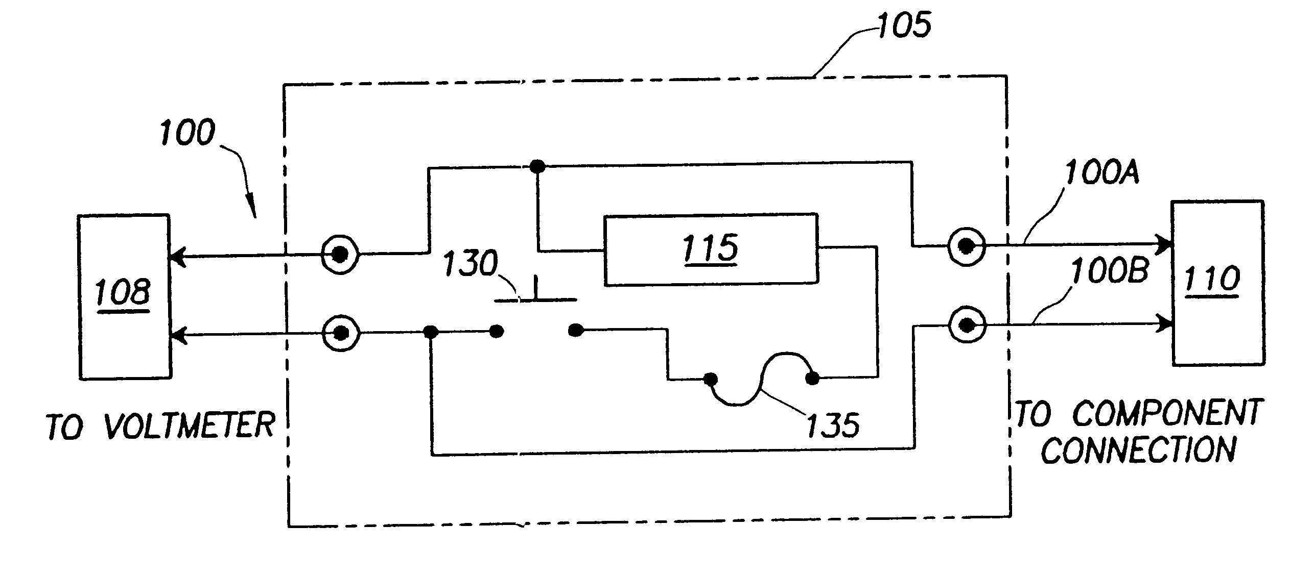
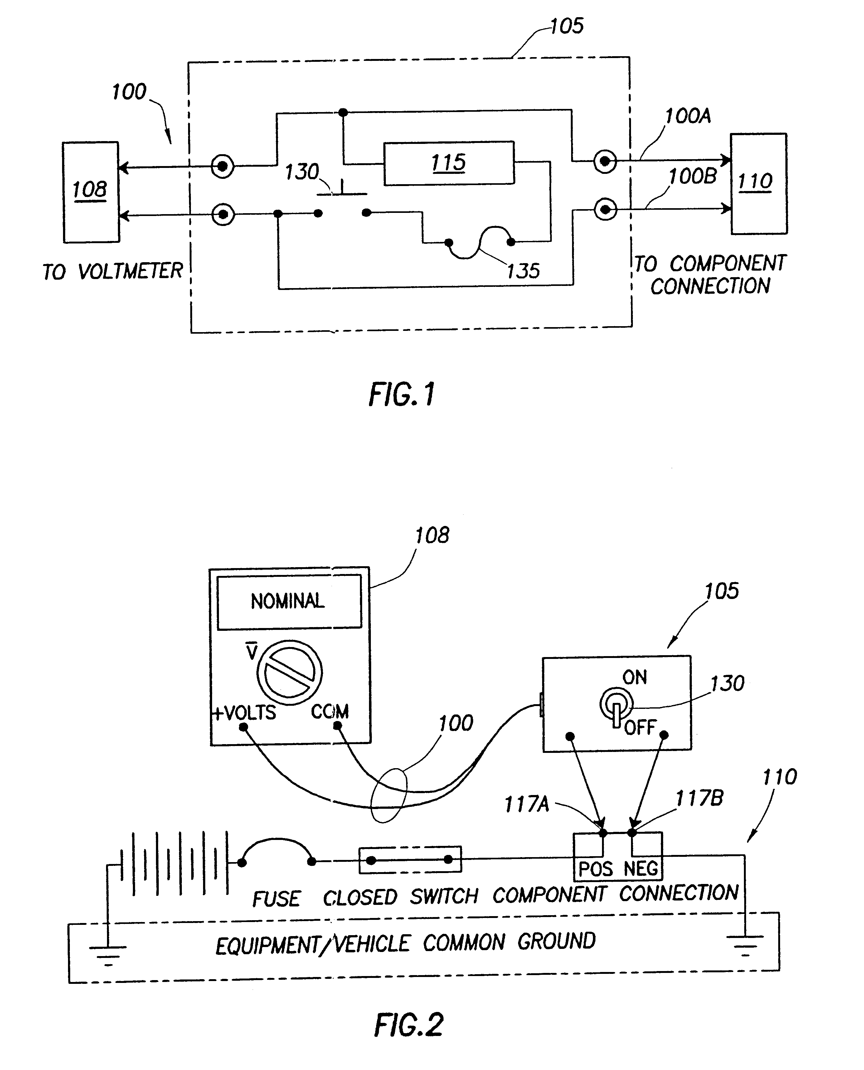
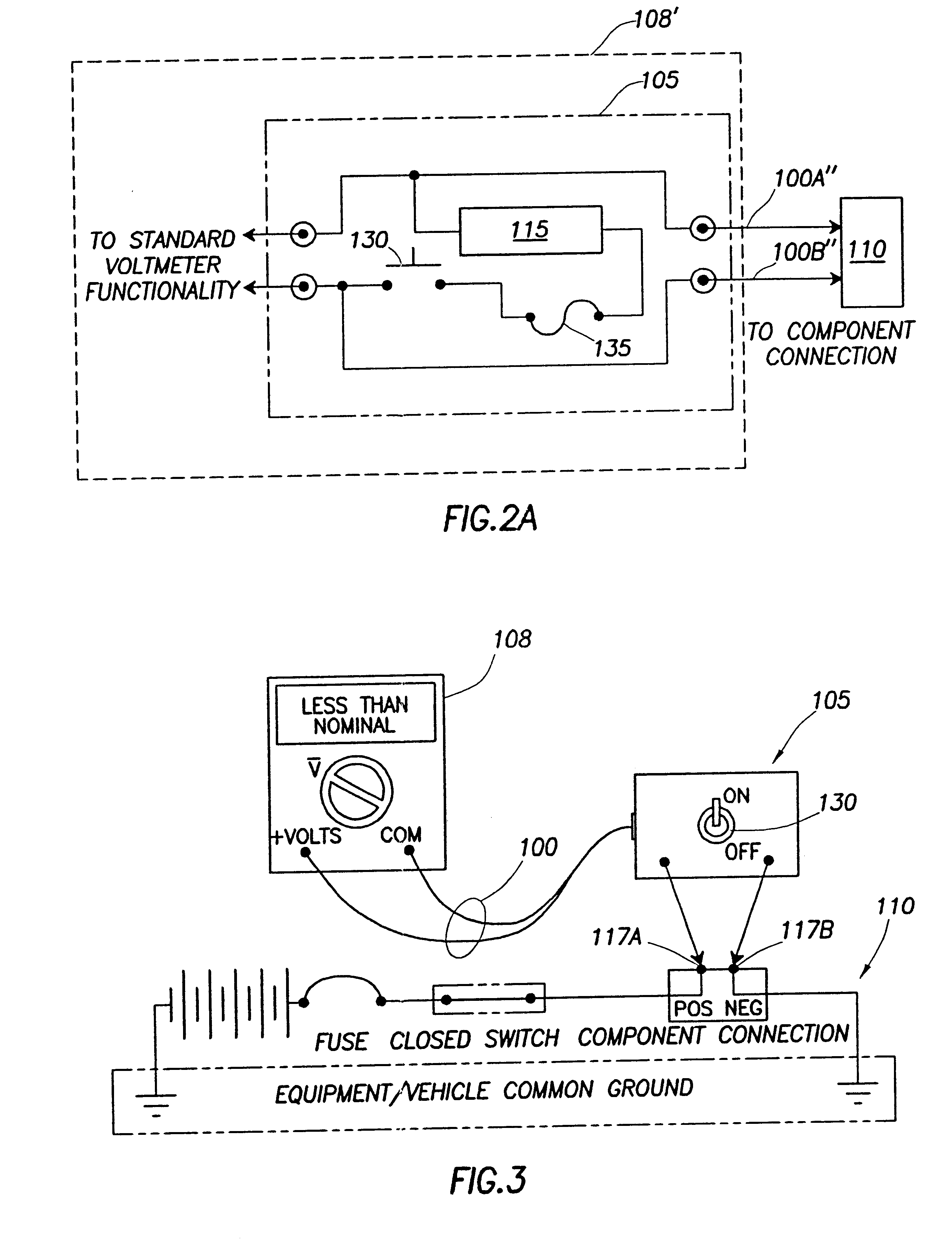
Enhanced voltmeter leads includes load circuitry having a test load that can be switchably coupled between the leads to help identify faults in a circuit under test. In certain embodiments, the value of the test load can be any appropriate value set according to parameters or characteristics of the circuit under test. In these embodiments, the value of the test load can be set manually or automatically or both. The types of faults that can be identified include a short-to-ground, an open circuit, and a high (e.g., corrosive) resistance. The leads include a switch whose setting is adjustable to couple and decouple the test load between the leads. The switch can be located in the leads or in a lead handle of the leads for easy access by a user / technician. The leads can also include a fuse or circuit breaker for safety reasons. The leads can be used systematically to help identify the type and location of a fault from voltage readings. The voltage readings are obtained at various points in the circuit under test with the switch both closed and open. Conventional test leads or the leads that include the switch to couple / decouple the test load can be used if the load circuitry is integrated into the voltmeter or if the load circuitry has a separate coupling or connection to the voltmeter inputs.

Description

1. Field of the InventionThe invention relates to enhancing voltmeter functionality, and more particularly, enhancing voltmeter functionality for isolating faults in electrical circuitry.2. Description of the Related ArtModem vehicles systems incorporate digital (computer) diagnostic systems that can detect many circuit faults in electrical components and systems (e.g., on vehicles). But such systems typically cannot detect all possible circuit faults, for example, high resistance faults caused by corrosion. Moreover, electrical troubleshooting on vehicles and other systems can be time-consuming, labor-intensive, costly, and often ineffective, especially if a component must be disconnected and / or removed for testing circuit continuity.The vast majority of circuit faults in wiring and connectors result from abuse, exposure, wear, and normal use. Failures in circuit wiring typically are caused by a change in circuit resistance and fall into one of three categories--an open circuit, a ...

Claims


Application Information

Patent Timeline
IPC IPC(8): G01R15/00G01R31/02G01R15/12G01R1/00G01R1/36G01R31/00G01R31/50
CPCG01R31/024G01R15/125G01R1/36G01R31/006G01R31/50
Inventor SULLIVAN, DANIEL B.
Owner SULLIVAN DANIEL B
Learn More