Stent delivery system with adjustable length balloon

Inactive Publication Date: 2005-04-26
ABBOTT CARDIOVASCULAR
View PDF22 Cites 120 Cited by
  • Summary
  • Abstract
  • Description
  • Claims
  • Application Information

AI Technical Summary

Benefits of technology

[0010]The present invention is directed to a stent delivery system which provides an expandable member (balloon) with a variable working length to accommodate a wide variety of stent lengths. Additionally, the invention provides an efficient and cost-effective post-expansion dilation solution for instances where a deployed stent or the lesion in the patient's anatomy requires additional dilation.
[0012]In one embodiment of the present invention, the adjustment member used to control the portion of expandable member that expands is an outer sheath with an inner lumen extending along the length thereof. The outer sheath includes a proximal section and a distal section, wherein the distal section is configured to envelop a stent mounted on an expandable member in a deflated condition. Because the distal section of the outer sheath is configured to envelop a stent mounted on the expandable member, the distal section may have a larger profile than the outer sheath proximal section. Preferably, the inner lumen of the distal section of the sheath has a larger internal diameter than the inner lumen of the proximal section of the sheath in order to facilitate receiving the expandable member in a deflated condition having a stent mounted thereon. The length of the distal section of the sheath that receives the expandable member should be at least one half of, but preferably as long as the length of the working surface of the expandable member. The sheath / dilitation catheter assembly is configured so that the sheath and the catheter are longitudinally moveable with respect to each other. The distal end of the sheath is provided with a greater degree of expandability so that when the expandable member is inflated the distal end of the sheath expands so as to shape the proximal taper of the expandable member. The sheath also is used to cover the collapsed stent to prevent it from moving axially along the expandable member of the dilatation catheter as the system is being deployed in the patient's vasculature. This sheath helps prevent the stent from being stripped off the delivery catheter or otherwise moved axially along the balloon length which can cause possible inaccurate placement during deployment. This sheath also acts as a protected covering which prevents the stent from abraiding the vessel wall as it is being delivered through the patient's vasculature.
[0014]Subsequent dilatations of the same stent may be required for areas of the stent which were not fully expanded upon the initial inflation of the expandable member. This post dilitation may require much higher pressure in a portion which was not completely expanded, because the stenosis at that portion was much harder than at other portions of the stent. Rather than subject the entire stent length to the higher pressure, the working length of the expandable member may be shortened (via the placement of the sheath over the expandable member) so that only the portion of the stent that had been incompletely expanded will be re-dilated. This avoids over-expansion and unnecessary injury in other areas of the stent or at the stent ends. Because there is an overall reduction of injury, and because pressure is focused only on the important areas, reduction of restenosis may be realized.
[0015]Additionally, the sheath supports the catheter and provides for improved pushability of the catheter, particularly with long expandable members, which have poor push transmission due to the long thin walled expandable member region of the distal shaft. An additional advantage of the sheath is that, after an initial dilation, the expandable member can be pulled back into the distal portion to re-groom the expandable member so that any wings, which may form when a vacuum is pulled on the interior of the expandable member, are wrapped about the inner tubular member extending through the interior of the expandable member rather than extend out laterally. This re-grooming reduces the effective profile of the deflated expandable member.

Problems solved by technology

This sheath helps prevent the stent from being stripped off the delivery catheter or otherwise moved axially along the balloon length which can cause possible inaccurate placement during deployment.

Method used


Image

  • Stent delivery system with adjustable length balloon
  • Stent delivery system with adjustable length balloon
  • Stent delivery system with adjustable length balloon

Examples


Embodiment Construction

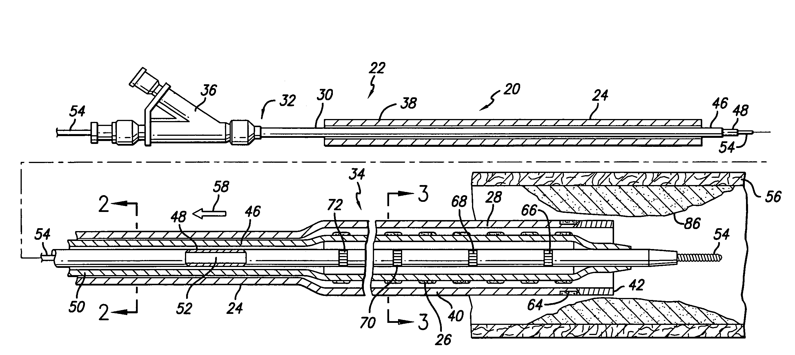
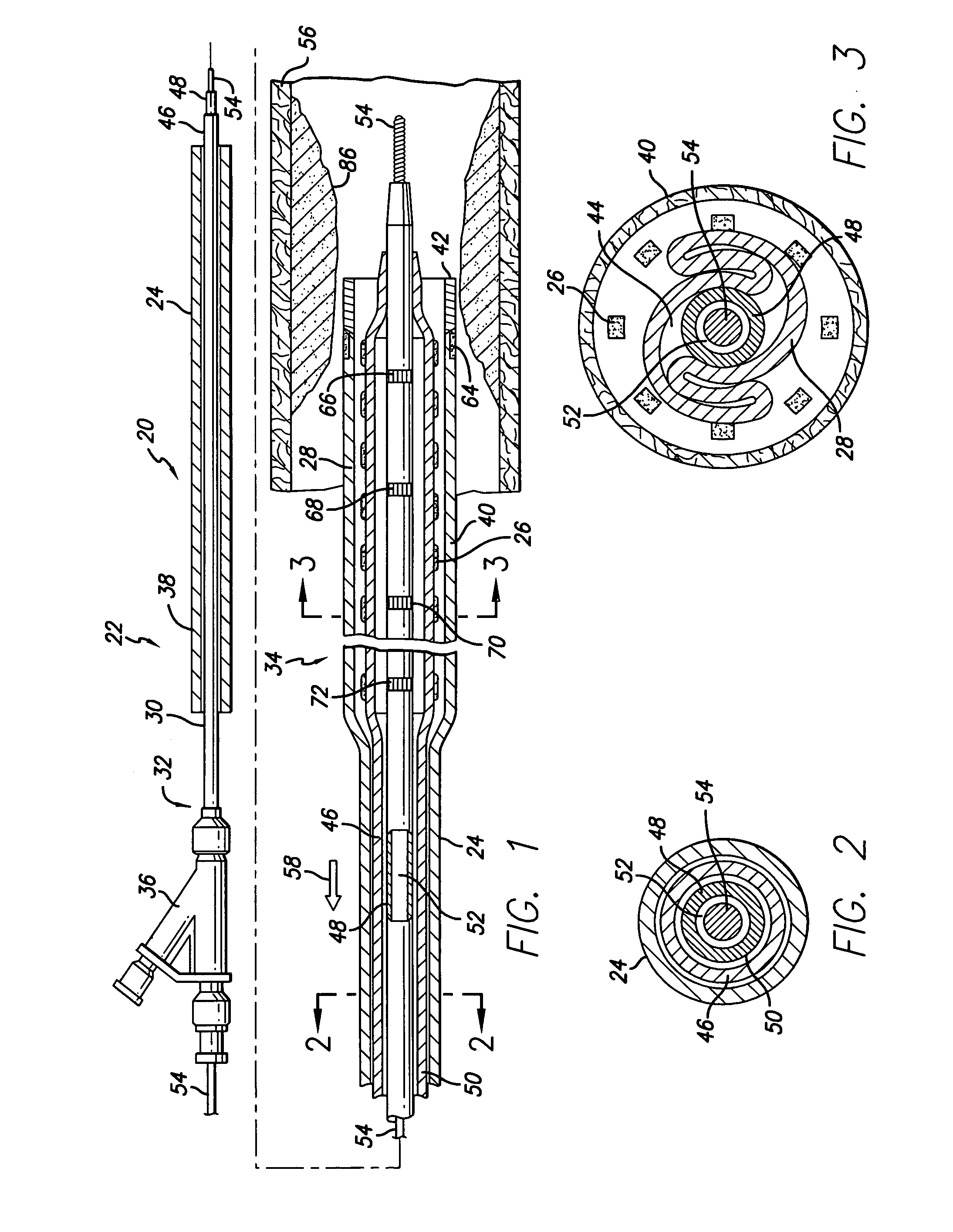
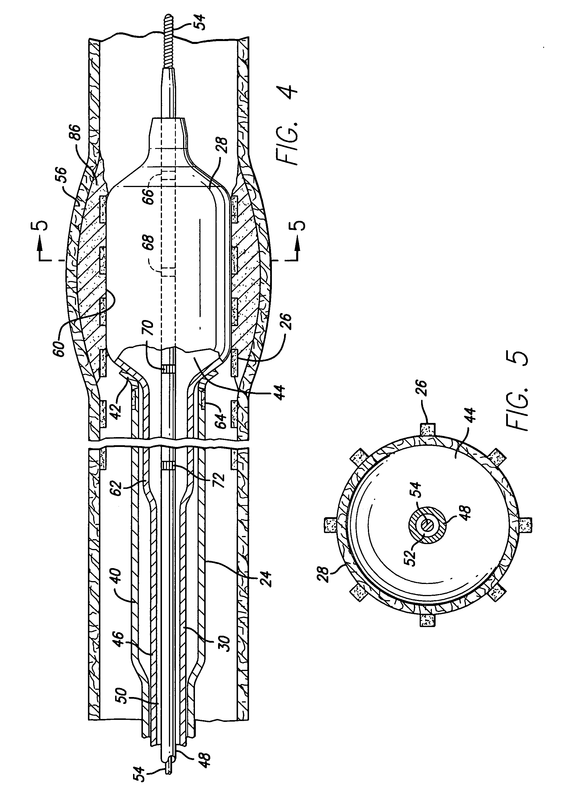
[0031]Turning now to the drawings, in which like reference numerals represent like or corresponding elements in the drawings, FIGS. 1–5 illustrate a catheter assembly 20 embodying features of the invention. The catheter assembly includes a delivery catheter 22, an adjustment member (sheath) 24 and a stent 26. The delivery catheter includes an expandable member 28 (such as an inflatable dilatation balloon), an elongate catheter shaft 30 having a proximal end 32 and a distal end 34, and an adapter (sidearm) 36 mounted on the catheter shaft proximal end. The sheath includes a proximal section 38, a distal section 40 and a distal tip 42. The outer sheath is disposed about and is capable of sliding over the delivery catheter. The outer sheath distal portion is slightly expanded and is adapted to receive the expandable member. The expandable member has a cavity 44, and to maintain the expanded distal portion 40 of the sheath as small as possible, the cavity of the expandable member is pre...


PUM


Abstract

A stent delivery system with an adjustable length balloon. The system includes a stent delivery catheter having an expandable member with an inflated length that can be adjusted according to the length of a stent to be expanded. An exterior sheath having an expandable distal tip is disposed about the expandable member such that the sheath can be longitudinally adjusted so as to expose a desired length of the expandable member. The exposed length of the expandable member provides an effective working length required to expand the stent for deployment. Additionally, where subsequent expansions of the deployed stent may be necessary, post dilitation may be achieved by re-positioning the catheter and re-adjusting the sheath to form an effective working length of the expandable member which corresponds to the length of the stent that needs further expansion.

Description

BACKGROUND OF THE INVENTION[0001]This invention relates to devices for the treatment of heart disease and particularly to endo-arterial prosthesis, which are commonly called stents. More particularly, the invention relates to a stent delivery system having an adjustable length balloon catheter for interventional treatment of diseased vessels.[0002]Several interventional treatment modalities are presently used for heart disease including balloon and laser angioplasty, atherectomy and by-pass surgery. In typical balloon angioplasty procedures, a guiding catheter having a performed distal tip is percutaneously introduced through the femoral artery into the cardiovascular system of a patient in a conventional Seldinger technique and advanced within the cardiovascular system until the distal tip of the guiding catheter is seated in the ostium. A guidewire is positioned within an inner lumen of a dilatation catheter and then both are advanced through the guiding catheter to the distal end...

Claims


Application Information

Patent Timeline
IPC IPC(8): A61F2/06A61F2/84
CPCA61F2/958A61F2/966A61F2002/9583
Inventor COX, DANIEL L.
Owner ABBOTT CARDIOVASCULAR
Why Eureka
Try Eureka