
Method and apparatus for disabling a clock signal within a multithreaded processor

Inactive Publication Date: 2005-04-19
INTEL CORP
View PDF8 Cites 100 Cited by
  • Summary
  • Abstract
  • Description
  • Claims
  • Application Information

AI Technical Summary

Benefits of technology

[0007]Where resource sharing is implemented within a multithreaded processor it is further desirable to attempt increased utilization of the shared resources responsive to changes in the state of threads being serviced within the multithreaded processor.
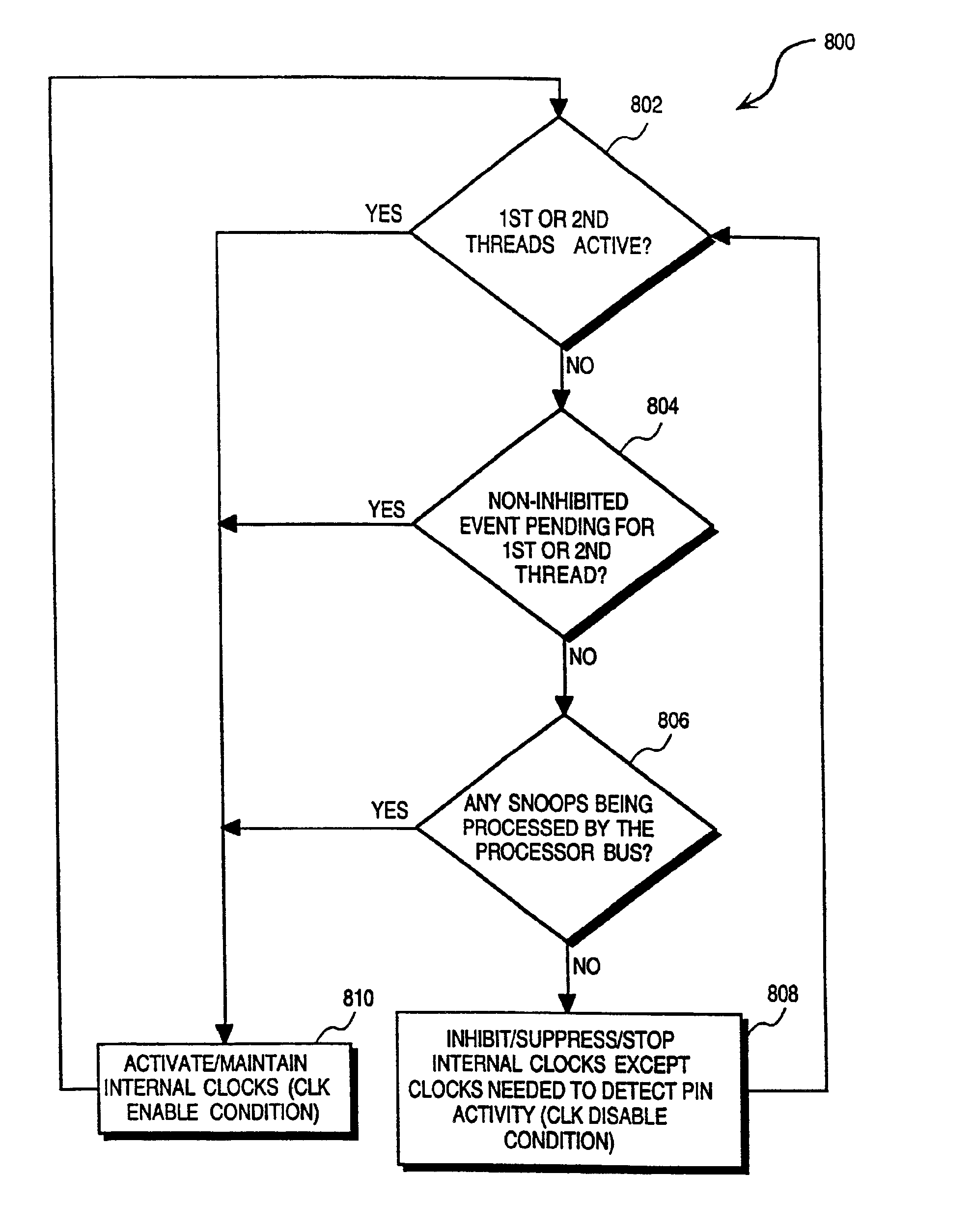
[0008]According to the present invention, there is provided a method that includes maintaining an indication of a pending event with respect to each of multiple threads supported within the multithreaded processor. An indicatio

Problems solved by technology

A stall in the processing of a particular thread may result from a number of occurrences within a processor pipeline.
For example, a cache miss or a branch misprediction (i.e., a long-latency operation) for an instruction included within a thread typically results in the processing of the relevant thread stalling.
The negative effect of long-latency operations on execution logic efficiencies is exacerbated by the recent increases in execution logic throughput that have outstripped advances in memory access and retrieval rates.
A multithreaded architecture for a processor presents a number of further challenges in the context of an out-of-order, speculative execution processor architecture.
More specifically, the handling of events (e.g., branch instructions, exceptions or interrupts) that may result in an unexpected change in the flow of an instruction stream is complicated when multiple threads are considered.
In a processor where resource sharing between multiple threads is implemented (i.e., there is limited or no duplication of functional units for each thread supported by the processor), the handling of event occurrences pertaining to a specific thread is complicated in that further threads must be considered in the handling of such events.

Method used


Image

  • Method and apparatus for disabling a clock signal within a multithreaded processor
  • Method and apparatus for disabling a clock signal within a multithreaded processor
  • Method and apparatus for disabling a clock signal within a multithreaded processor

Examples


Embodiment Construction

[0034]A method and apparatus for managing a clock signal within a multithreaded processor are described. In the following description, for purposes of explanation, numerous specific details are set forth in order to provide a thorough understanding of the present invention. It will be evident, however, to one skilled in the art that the present invention may be practiced without these specific details.

[0035]For the purposes of the present specification, the term “event” shall be taken to include any event, internal or external to a processor, that causes a change or interruption to the servicing of an instruction stream (macro- or microinstruction) within a processor. Accordingly, the term “event” shall be taken to include, but not be limited to, branch instructions processes, exceptions and interrupts that may be generated within or outside the processor.

[0036]For the purposes of the present specification, the term “processor” shall be taken to refer to any machine that is capable ...


PUM


Abstract

A method includes maintaining an indication of a pending event with respect to each of a number of threads supported within a multithreaded processor. An indication is also maintained of an active or inactive state for each of the multiple threads. A clock disable condition is detected. This clock disable condition may be indicated by the absence of pending events with respect to each of the multiple threads and an inactive state for each of the multiple threads. A clocks signal, if enabled, is then disabled with respect to at least one functional unit within the multithreaded processor responsive to the detection of the clock disable condition.

Description

CROSS REFERENCE TO RELATED APPLICATION[0001]This application is a continuation of patent application Ser. No. 09 / 458,589, filed Dec. 9, 1999, now U.S. Pat. No. 6,357,016.FIELD OF THE INVENTION[0002]The present invention relates generally to the field of multithreaded processors and, more specifically, to a method and apparatus for disabling a clock signal within a multithreaded (MT) processor.BACKGROUND OF THE INVENTION[0003]Multithreaded (MT) processor design has recently been considered as an increasingly attractive option for increasing the performance of processors. Multithreading within a processor, inter alia, provides the potential for more effective utilization of various processor resources, and particularly for more effective utilization of the execution logic within a processor. Specifically, by feeding multiple threads to the execution logic of a processor, clock cycles that would otherwise have been idle due to a stall or other delay in the processing of a particular th...

Claims


Application Information

Patent Timeline
IPC IPC(8): G06F9/38G06F15/00
CPCG06F1/3203G06F1/3237G06F1/3287G06F9/3851G06F9/384Y02B60/32Y02B60/1221Y02B60/1282Y02D10/00Y02D30/50
Inventor RODGERS, DIONTOLL, BRETWOOD, AIMEE
Owner INTEL CORP
Learn More