
Disk drive comprising asynchronous/synchronous gain control for fault tolerant detection of servo sync mark after head switch

Inactive Publication Date: 2005-04-19
WESTERN DIGITAL TECH INC
View PDF7 Cites 149 Cited by
  • Summary
  • Abstract
  • Description
  • Claims
  • Application Information

AI Technical Summary

Benefits of technology

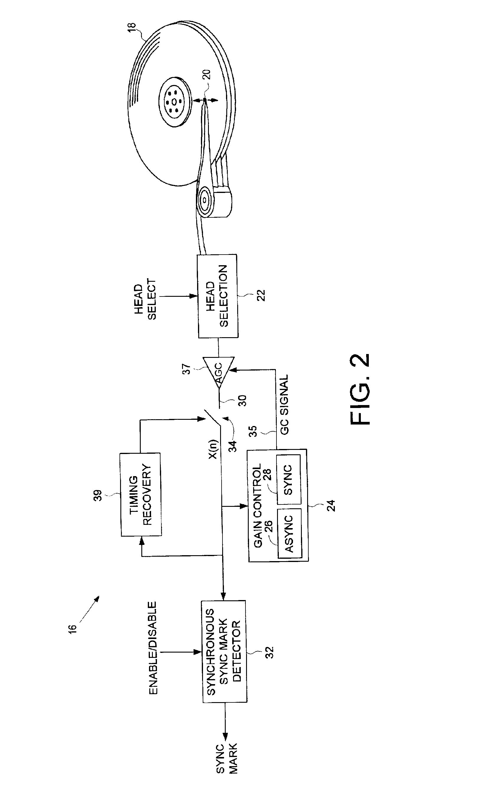
[0007]The present invention may be regarded as a disk drive comprising a plurality of disk surfaces each having a plurality of tracks, each track comprising a plurality of data sectors and a plurality of embedded servo sectors, each embedded servo sector comprising a servo sync mark for synchronizing to the embedded servo sector. The disk drive further comprises a plurality of heads actuated radially over respective disk surfaces, head selection circuitry for selecting one of the heads to perform a read or write operation, a gain control system implementing an asynchronous gain control algorithm and a synchronous gain control algorithm for controlling a gain of a read signal emanating from the selected head, and a synchronous sync mark detector for synchronously detecting the servo sync mark from the read signal. When the disk drive is synchronized to the embedded servo sectors of a first disk surface corresponding to the selected head, the synchronous sync mark detector is enabled relative to a detection window for detecting the servo sync marks recorded on the first disk surface. When the head selection circuitry selects another one of the heads corresponding to a second disk surface, the detection window is opened early to detect a servo sync mark recorded on the second disk surface. The asynchronous gain control algorithm prevents the gain control system from diverging due to the newly selected head reading an area of the second disk surface preceding the servo sync mark, and the synchronous gain control algorithm maintains a proper gain for the read signal while the newly selected head reads the servo sync mark.

Problems solved by technology

However, because small misalignments occur between the disks as well as the heads, the detection window may be opened too late and the servo sync mark 10 missed.

Method used


Image

  • Disk drive comprising asynchronous/synchronous gain control for fault tolerant detection of servo sync mark after head switch
  • Disk drive comprising asynchronous/synchronous gain control for fault tolerant detection of servo sync mark after head switch
  • Disk drive comprising asynchronous/synchronous gain control for fault tolerant detection of servo sync mark after head switch

Examples


Embodiment Construction

[0018]FIG. 2 shows a disk drive 16 according to an embodiment of the present invention comprising a plurality of disk surfaces 18 each having a plurality of tracks, each track comprising a plurality of data sectors and a plurality of embedded servo sectors, each embedded servo sector comprising a servo sync mark for synchronizing to the embedded servo sector. The disk drive 16 further comprises a plurality of heads 20 actuated radially over respective disk surfaces, head selection circuitry 22 for selecting one of the heads 20 to perform a read or write operation, a gain control system 24 implementing an asynchronous gain control algorithm 26 and a synchronous gain control algorithm 28 for controlling a gain of a read signal 30 emanating from the selected head 20, and a synchronous sync mark detector 32 for synchronously detecting the servo sync mark from the read signal 30. When the disk drive 16 is synchronized to the embedded servo sectors of a first disk surface, the synchronous...


PUM


Abstract

A disk drive is disclosed comprising a plurality of disk surfaces and a plurality of respective heads actuated radially over the disk surfaces. Each disk surface comprises a plurality of tracks, each track comprising a plurality of data sectors and a plurality of embedded servo sectors, each embedded servo sector comprising a servo sync mark for synchronizing to the embedded servo sector. When the disk drive switches heads, a detection window for detecting the servo sync mark is opened early. An asynchronous gain control algorithm prevents a gain control system from diverging while reading an area of the disk surface preceding the servo sync mark, and a synchronous gain control algorithm maintains a proper gain of the read signal while reading the servo sync mark.

Description

BACKGROUND OF THE INVENTION[0001]1. Field of the Invention[0002]The present invention relates to disk drives for computer systems. More particularly, the present invention relates to a disk drive comprising asynchronous / synchronous gain control for fault tolerant detection of servo sync mark after a head switch.[0003]2. Description of the Prior Art[0004]Disk drives may comprise multiple disks with corresponding heads for accessing a top and bottom surface of each disk. Typically only one head is active at a time for reading data from or writing data to a particular disk surface. FIG. 1 illustrates a prior art format for a disk surface 2 comprising a plurality of radially spaced, concentric tracks 4. Each track 4 comprises a plurality of data sectors and a plurality of embedded servo sectors 6. Each servo sector 6 comprises a preamble 8 for synchronizing gain control and timing recovery, a sync mark 10 for synchronizing to a data field 12 comprising coarse head positioning informatio...

Claims


Application Information

Patent Timeline
IPC IPC(8): G11B20/10G11B5/09G11B19/04G11B27/30
CPCG11B5/09G11B19/04G11B20/10027G11B27/3027G11B20/10009G11B2220/20
Inventor KUPFERMAN, HANAN
Owner WESTERN DIGITAL TECH INC
Learn More