
Optical compensation film, viewing angle compensation integral type polarizing plate and liquid crystal display apparatus

a liquid crystal display and integral type technology, applied in the direction of polarising elements, instruments, domestic cooling devices, etc., can solve the problems of image degradation, dimensional variation during storage, and the problem of not completely solving the above-mentioned method, and achieve excellent viewing angle compensation function and enhance the durability of the viewing angle compensation function

Active Publication Date: 2005-04-19
KONICA MINOLTA INC
View PDF5 Cites 33 Cited by
  • Summary
  • Abstract
  • Description
  • Claims
  • Application Information

AI Technical Summary

Benefits of technology

The present invention provides an optical compensation film that can enhance the viewing angle compensation function and improve durability during storage. The film has specific properties, including a cellulose ester film with low photoelastic coefficients and retardation values, and an optically anisotropic layer with a fixed orientation structure. The film can be used in a viewing angle compensation integral type polarizing plate and a liquid crystal display apparatus, providing better viewing angles and image quality. The invention also provides a support for the optical compensation film with improved durability.

Problems solved by technology

The resulting image degradation is due to viewing angle characteristics inherent in liquid crystal display apparatuses.
However, it has been found that problems are not completely solved employing the aforesaid method.
The aforesaid residual strain results in dimensional variation during storage.
As a result, in practice, critical problems have occurred in which the polarizing plate, adhered onto the liquid crystal cell, peels off.
The resulting stress varies the retardation of the film and markedly affects viewing angle compensation characteristics during storage.
As a result, in view of durability of the viewing angle characteristics, critical problems have practically occurred.

Method used


Image

  • Optical compensation film, viewing angle compensation integral type polarizing plate and liquid crystal display apparatus
  • Optical compensation film, viewing angle compensation integral type polarizing plate and liquid crystal display apparatus
  • Optical compensation film, viewing angle compensation integral type polarizing plate and liquid crystal display apparatus

Examples


example 1

(Preparation of Dope A)

[0174]One part by weight of Aerosil R972 and 9 parts by weight of ethanol were blended in a vessel, and the resulting mixture was finely dispersed employing a Manton-Gaulin homogenizer with a shearing force of 30 MPa to prepare a minute particle stock composition. Subsequently, the resulting stock composition was diluted by 9 parts by weight of methylene chloride in a pressure proof sealed vessel, and the resulting mixture was designated as a filler dispersion diluted liquid composition.

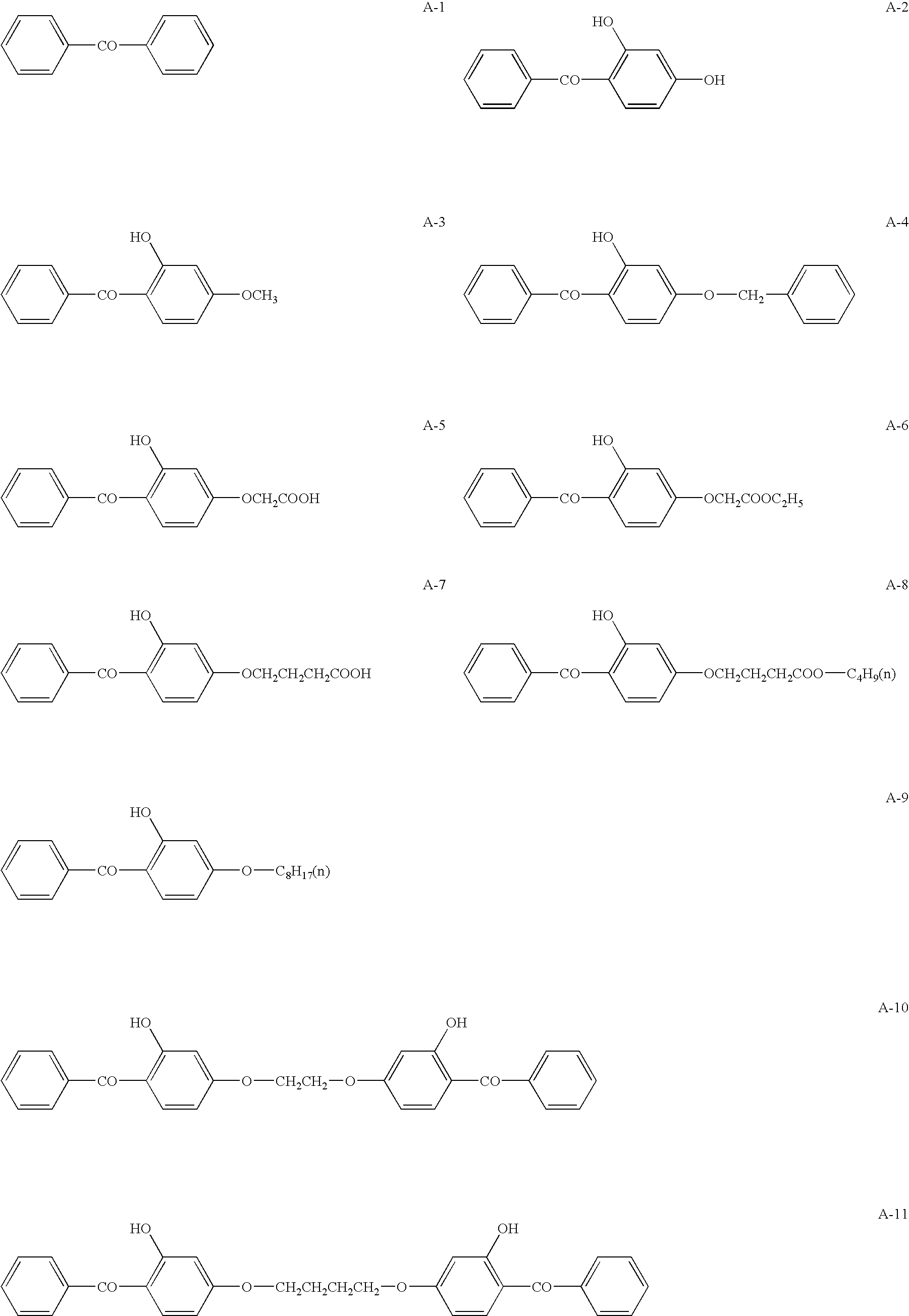
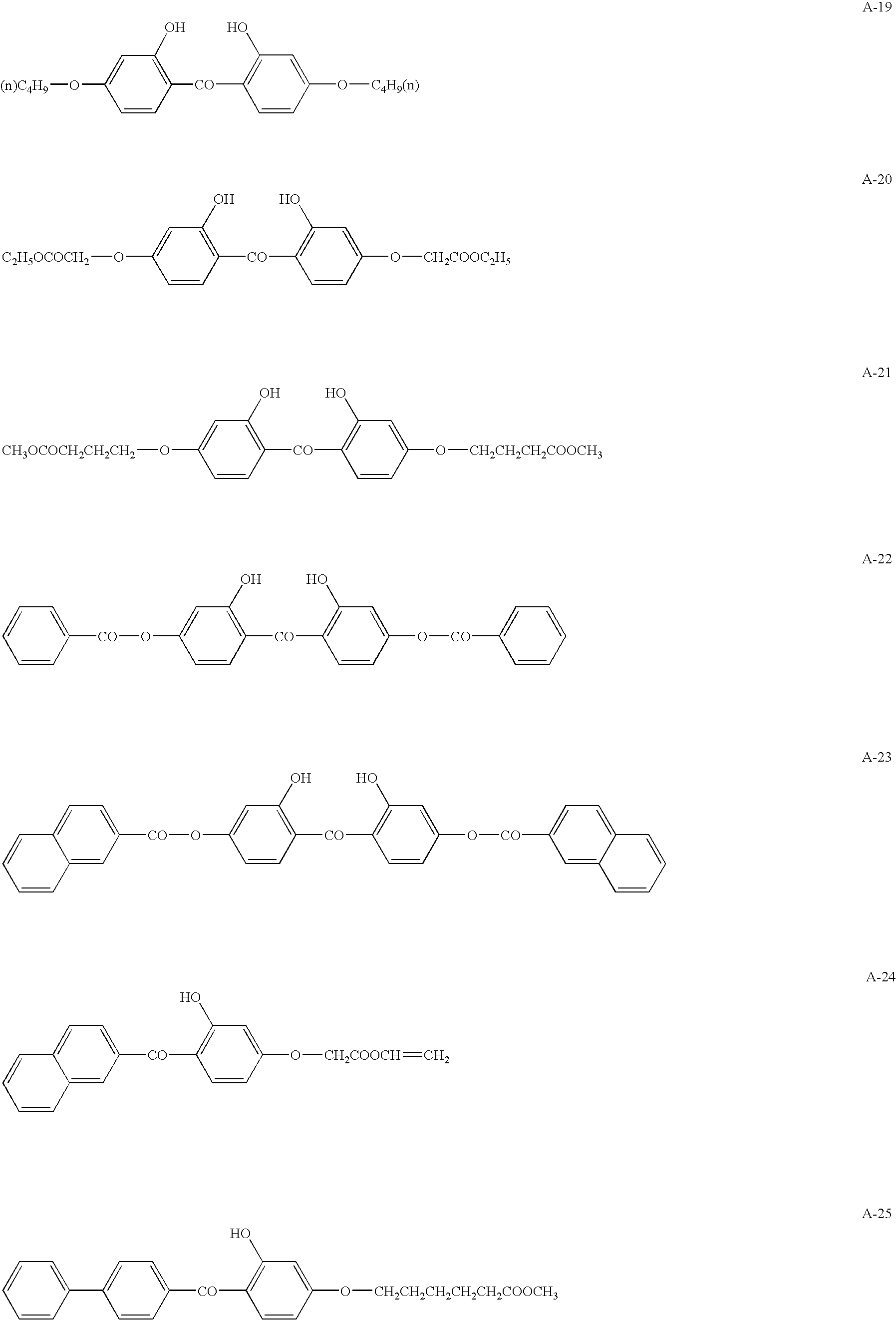
[0175]Dissolved in 14.2 parts by weight of methylene chloride were 1.2 parts by weight of a UV absorber and 0.7 part by weight of cellulose ester (described in A of Table 1), and 3.0 parts by weight of the aforesaid filler dispersion diluted liquid composition was added while stirring. The resulting mixture was designated as a filler addition liquid composition. The cellulose ester solution composition described below was introduced into another pressure proof sealed vessel, wh...

example 2

[0195]Alkyl-modified polyvinyl alcohol (0.1 μm) was applied onto one side of each of Viewing Angle Compensation Integral Type Polarizing Plates E and G and dried by 65° C. air flow. Thereafter, an orientation layer was prepared by carrying out a rubbing treatment parallel to the mechanical direction (the absorption axis direction of the polarizer) of the film.

[0196]Further, Solution LC-1 having the composition described below was applied onto the orientation layer. The resulting orientation was firmly fixed by exposure to 450 mL / cm3 of ultraviolet radiation under the condition of an oxygen concentration of at least 0.1 percent. Subsequently, an optically anisotropic layer having a nematic hybrid structure was applied onto one side, whereby Viewing Angle Compensation Polarizing Plates L and O were prepared corresponding to each of Viewing Angle Compensation Integral Type Polarizing Plates E and G. The aforesaid treatments were carried out through roller conveyance.

[0197]The optically...

example 3

[0200]Alkyl-modified polyvinyl alcohol (0.1 μm) was applied onto one side of each of Viewing Angle Compensation Integral Type Polarizing Plates E, G, M, and N and dried by 65° C. air flow. Thereafter, an orientation layer was prepared by carrying out a rubbing treatment parallel to the mechanical direction (the absorption axis direction of the polarizer) of the film.

[0201]Dissolved in 102 g of methyl ethyl ketone were 41.01 g of the discotic liquid crystal compound described below, 4.06 g of ethylene oxide-modified trimethylolpropane triacrylate (V#360, manufactured by Osaka Organic Chemical Industry Ltd.), 0.90 g of cellulose acetate butyrate (CAB551-0.2, manufactured by Eastman Chemical Co.), 0.23 g of cellulose acetate butyrate (CAB531-1, manufactured by Eastman Chemical Co.), 1.35 g of a photopolymerization initiator (Irugacure 907, manufactured by Ciba-Geigy Corp.), and 0.45 g of a sensitizer (Kayacure DETX, manufactured by Nippon Kayaku Co., Ltd.), whereby a liquid coating com...


PUM

PropertyMeasurementUnit
thicknessaaaaaaaaaa
angleaaaaaaaaaa
angleaaaaaaaaaa

Abstract

An optical compensation film comprising a cellulose ester film is disclosed. In the film, (a) each of photoelastic coefficient C(md) in a mechanical direction and photoelastic coefficient C(td) in the transverse direction of the cellulose ester film is 1×10⁻⁹ to 1×10⁻¹³ Pa−1 and C(md)<C(td), (b) retardation R0 within the plane of the cellulose film defined by Formula (I) is 20 to 70 nm, (c) retardation Rt of the cellulose ester film in a thickness direction, defined by Formula (II) is 70 to 400 nm, and (d) both of a dimensional variation ratio S(md) in the mechanical direction and a dimensional variation ratio S(td) in the transverse direction of the cellulose ester film prior to and after being allowed to stand at ambient conditions of 80° C. and 90 percent relative humidity for 50 hours are −1 to 1 percent, and |S(md)|>|S(td)|.

Description

BACKGROUND OF THE-INVENTION[0001]The present invention relates to an optical compensation film, an optical compensation film support, a viewing angle compensation integral type polarizing plate, and a liquid crystal display apparatus.[0002]Currently, cellulose acetate film (represented by cellulose triacetate film) is widely employed to prepare silver halide light-sensitive photographic materials as well as optical films due to its desirable characteristics such as high transparency as well as minimal optical drawbacks. Particularly, cellulose acetate film is preferably employed as a polarizing plate protective film for liquid crystal display apparatuses.[0003]Incidentally, when images on a crystal liquid display apparatus are viewed from an oblique direction, image quality is degraded compared to that when viewed directly from the front. The resulting image degradation is due to viewing angle characteristics inherent in liquid crystal display apparatuses. In order overcome this dra...

Claims


Application Information

Patent Timeline
Patent Type & Authority Patents(United States)
IPC IPC(8): C09K19/32G02B5/30G02F1/1335
CPCC09K19/32G02B5/3083C09K2019/328Y10T428/105Y10T428/10Y10T428/1036C09K2323/035C09K2323/03C09K2323/00F25D23/065A61L9/20
Inventor TASAKA, KOJIYAJIMA, TAKATOSHIKUZUHARA, NORIYASUUMEDA, HIROKI
Owner KONICA MINOLTA INC
Learn More