
Compressor within motor rotor

a compressor and motor rotor technology, applied in the direction of positive displacement liquid engines, piston pumps, liquid fuel engines, etc., can solve the problems of increasing the moment of inertia, increasing the vibration noise of the compressor, and requiring a large amount of installation space for the compressor, and achieves the effect of small size and simple structur

Inactive Publication Date: 2005-04-19
LG ELECTRONICS INC
View PDF6 Cites 18 Cited by
  • Summary
  • Abstract
  • Description
  • Claims
  • Application Information

AI Technical Summary

Benefits of technology

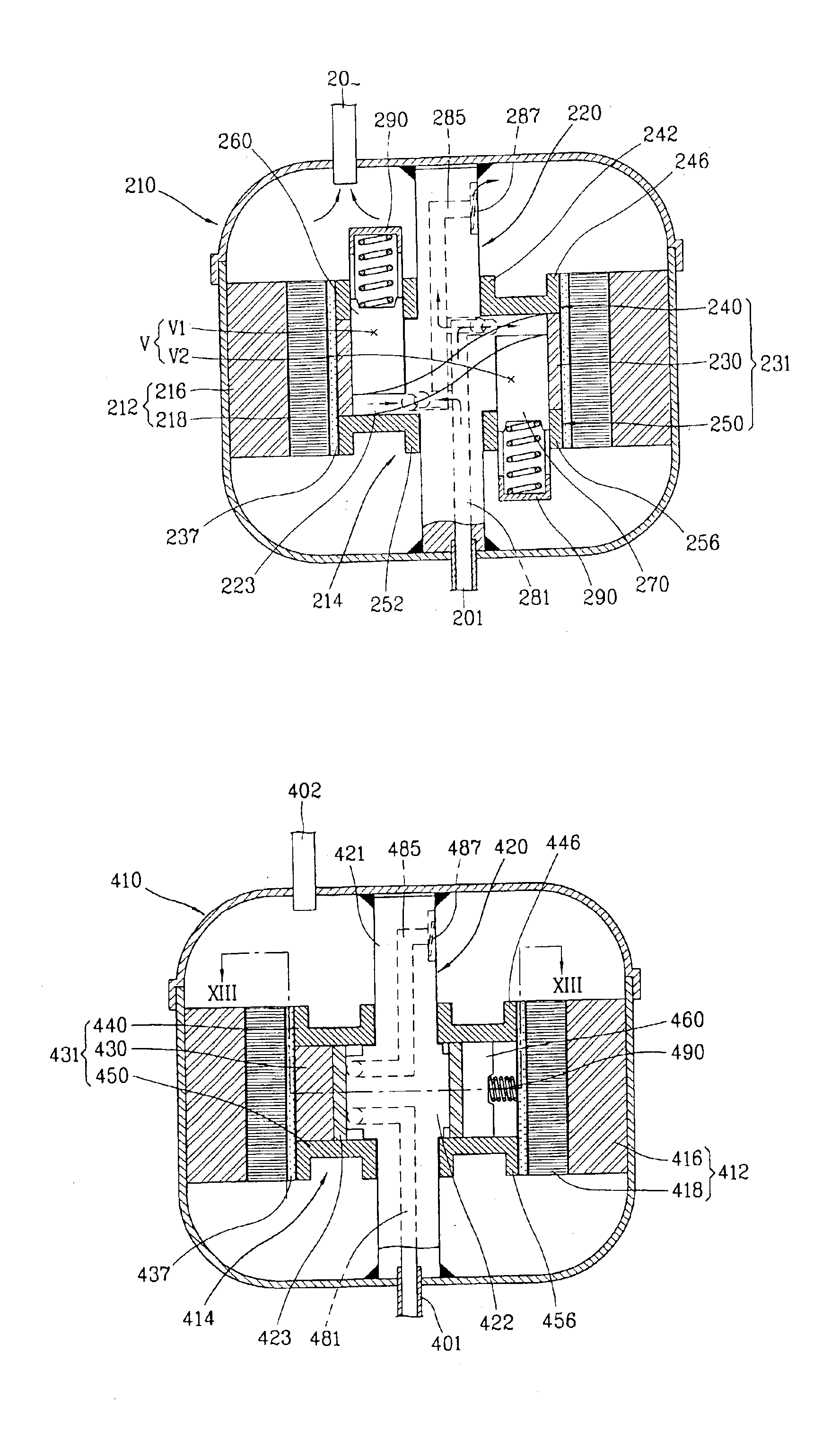
[0041]Therefore, it is an object of the present invention to provide a compressor with a simple structure and a small size by disposing a compression unit in a rotor of a motor unit to make a stator and a cylinder assembly a single body.

Problems solved by technology

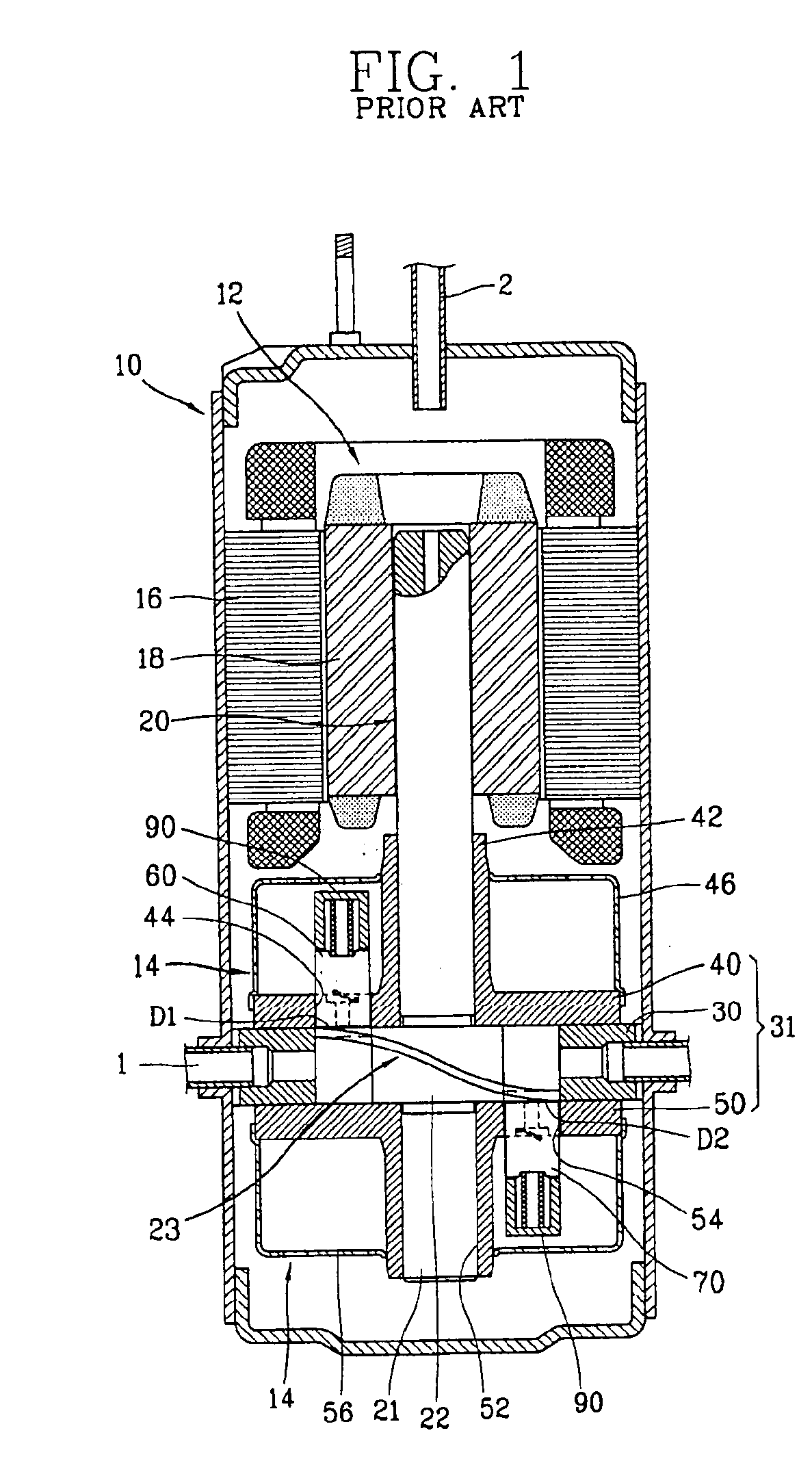
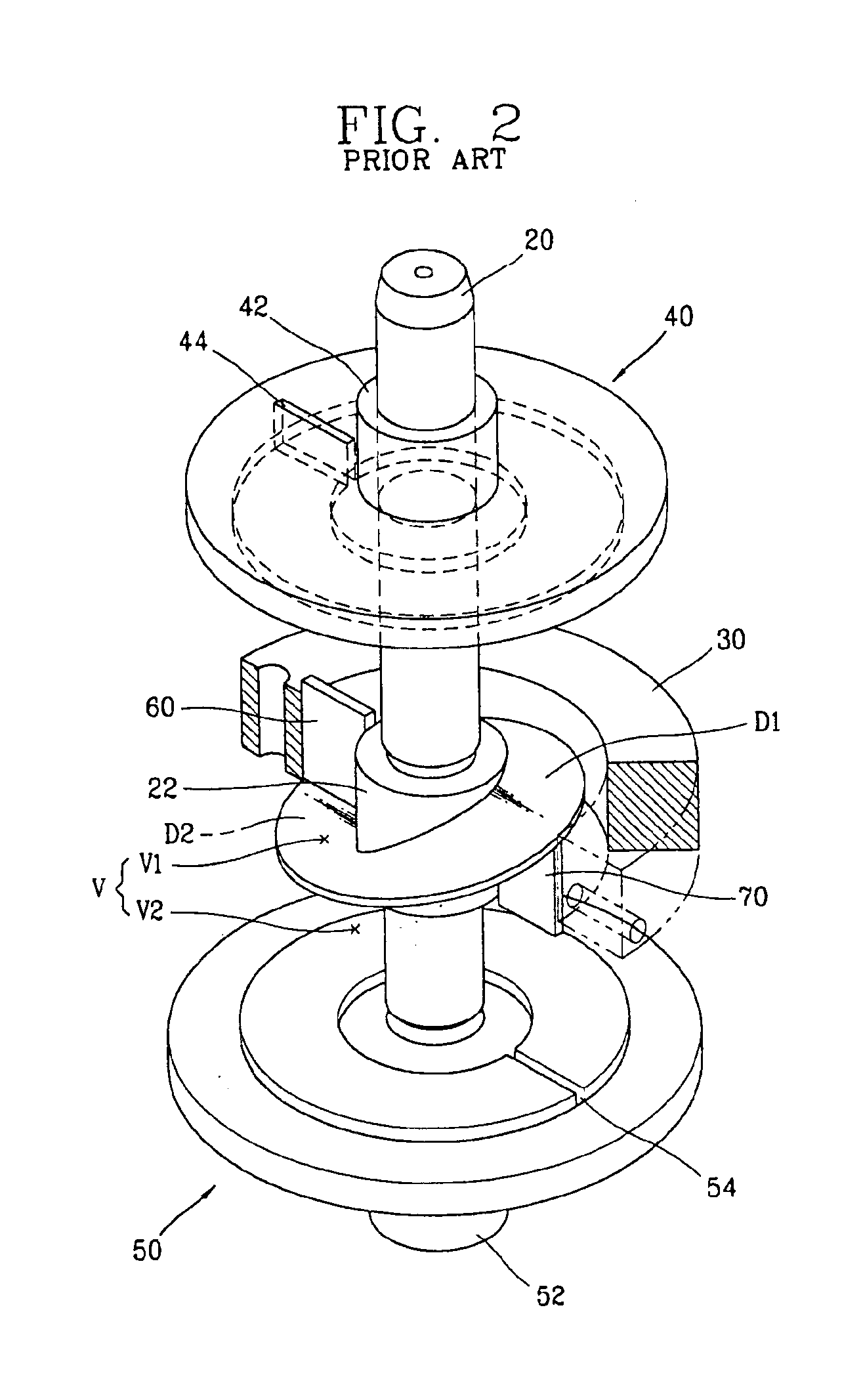
Also, as the transmission length of the rotating power is increased as above, the moment of inertia is increased, and accordingly, vibration noise of the compressor is also increased.
However, the conventional compressor is formed long in the length direction, and therefore, a lot of installation space is required for the compressor.

Method used


Image

  • Compressor within motor rotor
  • Compressor within motor rotor
  • Compressor within motor rotor

Examples


Embodiment Construction

[0055]Hereinafter, preferred embodiments of a compressor according to the present invention will be described with reference to accompanying Figures as follows.

[0056]FIG. 5 is a longitudinal cross-sectional view showing a compressor according to the present invention, FIG. 6 is a perspective view showing a part of a compression unit in the compressor shown in FIG. 5.

[0057]As shown in FIGS. 5 and 6, the compressor according to the present invention roughly comprises a sealed chamber 210 to which a suction pipe 201 and a discharge pipe 202 are connected, a motor unit 212 disposed in the sealed chamber 210 for generating a driving force, and a compression unit 214 inserted into the motor unit 21 for compressing compressible fluid.

[0058]The motor unit 212 comprises a stator 216 fixedly adhered to an inner circumferential surface of the sealed chamber 210, and a rotor 218 disposed to maintain a certain air gap with the stator 216 to be rotated by an electromagnetic interaction with the s...


PUM


Abstract

A compressor comprises a sealed chamber to which a suction pipe and a discharge pipe are communicated, a motor unit fixed in the sealed chamber and consisting of a stator and a rotor for generating rotating force by electromagnetic interaction between the stator and rotor, and a compression unit sucking, compressing and discharging compressible fluid according regular volume change and opening / closing of valve caused by rotating force of the motor unit, wherein the compression unit is disposed in the rotor to miniaturize and lighten the compressor, to reduce input energy of the motor unit, and to reduce vibration noise.

Description

TECHNICAL FIELD[0001]The present invention relates to a compressor using a vane, and particularly, to a compressor of which a structure is simplified to reduce a volume, weight and production cost of the compressor.BACKGROUND ART[0002]Generally, a compressor is a device for changing a mechanical energy into a compressive energy of compressible fluid. And a refrigerating compressor can be classified into a reciprocating compressor, a scroll compressor, a centrifugal type compressor, and a rotary compressor.[0003]Among those compressors, a compressor which reciprocates in a compression space, in which a volume is formed eccentrically, and divides the compression space into a suction area and a compression area will be described as follows.[0004]FIG. 1 is a longitudinal cross-sectional view showing an example of the compressor according to the conventional art, and FIG. 2 is a cut perspective view showing a compression unit of the compressor in FIG. 1.[0005]The compressor shown in FIGS...

Claims


Application Information

Patent Timeline
Patent Type & Authority Patents(United States)
IPC IPC(8): F04C29/00F04C23/00F04C18/356F04B39/00
CPCF04C18/3568F04C29/0085F04C23/008F04B39/00F04C18/00F04C29/00
Inventor LEE, CHANG-SOO
Owner LG ELECTRONICS INC
Learn More