
Apparatus for the enhancement of water quality in a subterranean pressurized water distribution system

a water distribution system and water sampling technology, applied in water mains, service pipe systems, machines/engines, etc., can solve the problems of degrading the chemical and microbiological quality of water transported through the distribution system, further exacerbated problems, and degradation of water quality, so as to reduce the present human resource requirements, maintain water quality, and reduce the effect of human resource requirements

Inactive Publication Date: 2005-04-19
MUELLER INT LLC
View PDF44 Cites 39 Cited by
  • Summary
  • Abstract
  • Description
  • Claims
  • Application Information

AI Technical Summary

Benefits of technology

[0014]Aspects of the invention provide an efficient and cost-effective means for maintaining water quality in low flow or dead end areas of an underground water distribution system. The invention generally embodies an apparatus for the automated analysis of water samples and purging of low quality water from such areas on an as-need basis. The apparatus greatly reduces present human resource requirements associated with performing these functions.
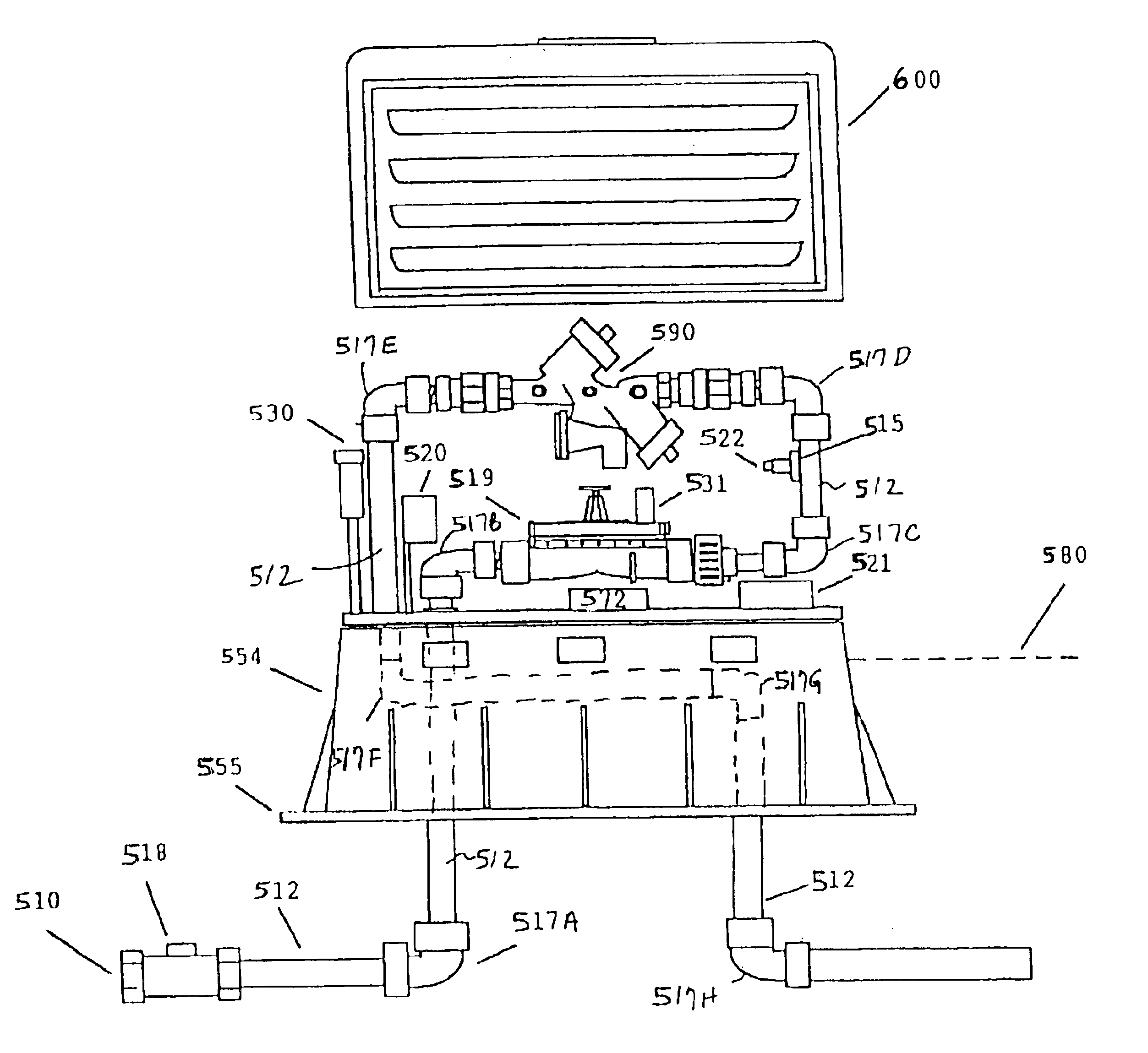
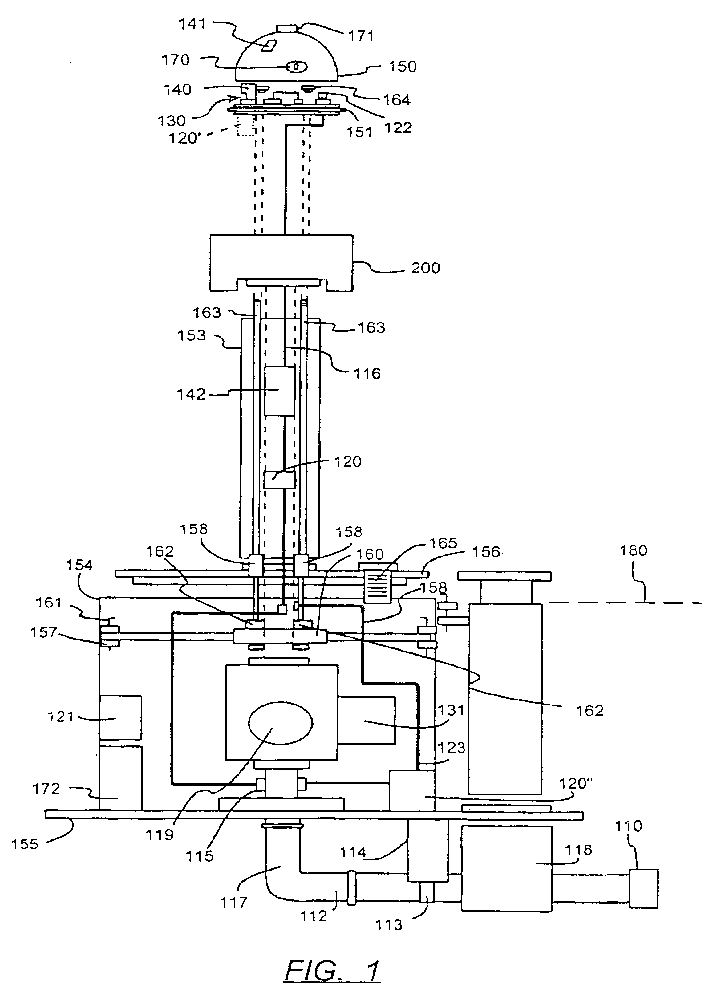
[0020]An apparatus according to the first embodiment of the invention, like that shown in FIG. 1, can provide for a downwardly directed discharge above ground. This discharge approach provides several advantages including the avoidance of dangers to passing pedestrians and traffic from high pressure discharge.

Problems solved by technology

For instance, fire protection and land development codes often require oversized water mains for anticipated fire control and peak water demands.
The problem is further exacerbated by water distribution systems that experience large seasonal fluctuations in demand.
Low water flow conditions and corresponding increases in water retention time within portions of the water distribution system have the potential to degrade the chemical and microbiological quality of water transported through the distribution system.
Degradation in water quality results from prolonged exposure to water system materials, internal sedimentation, and / or contaminant deposits within the piping system.
However, as disinfectant residuals dissipate bacterial regrowth occurs.
Water systems failing to adhere to regulatory or operational water quality standards are subject to regulatory enforcement action, public disclosure of health hazards, and increased public and regulatory scrutiny.
Corrosive water tends to dissolve certain materials commonly used in the construction of water distribution systems.
Elevated iron concentrations can result in violations of drinking water standards.
In both potable and non-potable water distribution systems, excessive concentrations of iron can result in staining of structure surfaces, fixtures and clothing.
Bacterial hazards also abound in low flow or dead end portions of water distribution systems.
Removal of such films is expensive and time consuming.
These designated sampling locations often produce test results that are either inaccurate or not representative of water quality throughout the water distribution system.
This method does not provide an adequate solution, since its success is contingent on financial and human resource availability.
The prior art does not provide an adequate solution for addressing the aforementioned water quality degradation problems common at low flow and dead end areas of water distribution systems.
Further, manual purging of low quality water causes excessive amounts of water to be discharged from the system thus making operation impractical in areas of poor drainage and high pedestrian / vehicular traffic.

Method used


Image

  • Apparatus for the enhancement of water quality in a subterranean pressurized water distribution system
  • Apparatus for the enhancement of water quality in a subterranean pressurized water distribution system
  • Apparatus for the enhancement of water quality in a subterranean pressurized water distribution system

Examples


Embodiment Construction

[0028]While the specification concludes with claims defining the features of the invention that are regarded as novel, it is believed that the invention will be better understood from a consideration of the following description in conjunction with the drawing figures, in which like reference numerals are carried forward.

[0029]Referring to FIG. 1, a multicomponent apparatus is provided for measuring the water quality of a subterranean water distribution system and selectively purging water therefrom. The apparatus is adapted for above and below ground, or grade level 180, mounting. As used herein, the term “upper portion” denotes structure located above grade level 180, and the term “lower portion” denotes structure located below grade level 180. In the preferred embodiment, the major components of the apparatus include: a housing; water transport apparatus; a programmable solenoid controller; a programming / data retrieval port; an electronic data control system; chemical, electronic...


PUM

PropertyMeasurementUnit
dissipate energyaaaaaaaaaa
erosionaaaaaaaaaa
flow areaaaaaaaaaaa

Abstract

An apparatus for the enhancement of water quality is provided for purging a low flow area of a subterranean water distribution system. The apparatus can include: a water carrier system for transporting water through the apparatus, a flow control valve for adjusting the flow rate of water through the system; a programmable solenoid controller for activating and deactivating the flow control valve; electronic and / or optical sensing devices for measuring water quality; a data access and programming port; and an electronic control system. The components cooperate to provide a means for automatically measuring water quality and then purging water from the low flow area as required. The apparatus can discharge directly to a below ground drain such as a storm drain, sewer or drain field. Alternatively, the apparatus can have an above ground downwardly directed discharge.

Description

CROSS REFERENCE TO RELATED APPLICATIONS[0001]This application is a continuation of application Ser. No. 10 / 021,742, filed on Dec. 12, 2001, now U.S. Pat. No. 6,635,172, which is a continuation of Application Ser. No. 09 / 525,203, filed on Mar. 14, 2000, now U.S. Pat. No. 6,358,408, which is a continuation-in-part of application Ser. No. 09 / 096,626, filed on Jun. 12, 1998, now U.S. Pat. No. 6,035,704.STATEMENT REGARDING FEDERALLY SPONSORED RESEARCH OR DEVELOPMENT[0002](Not Applicable)FIELD OF THE INVENTION[0003]The invention relates in general to water quality maintenance devices and more particularly to a water sampling and purging apparatus for automatically maintaining water quality in a low flow area of an underground water distribution system.BACKGROUND OF THE INVENTION[0004]Traditional underground water distribution systems for residential and commercial areas often incorporate low flow or dead end portions by design. For instance, fire protection and land development codes ofte...

Claims


Application Information

Patent Timeline
Patent Type & Authority Patents(United States)
IPC IPC(8): E03B7/00E03B7/09G01N33/18B01D17/12
CPCE03B7/006E03B7/08G01N33/18Y10T137/402Y10T137/7043Y10T137/8158Y10T137/8593
Inventor NEWMAN, MICHAEL R.
Owner MUELLER INT LLC
Learn More