
Static air mixing apparatus

a technology of air mixing apparatus and air compressor, which is applied in the direction of lighting and heating apparatus, ventilation systems, heating types, etc., can solve the problems of significant affecting the cost of operating and maintaining a hvac system, the complexity of air mixers, and the inability to meet the needs of the user, so as to reduce manufacturing costs, reduce manufacturing costs, and improve the effect of mixing effectiveness

Inactive Publication Date: 2005-04-12
BLENDER PROD
View PDF10 Cites 16 Cited by
  • Summary
  • Abstract
  • Description
  • Claims
  • Application Information

AI Technical Summary

Benefits of technology

"The present invention provides an improved static air mixing apparatus that achieves acceptable mixing effectiveness while reducing manufacturing costs. The design of the mixer is simplified by using curved vanes with inner and outer sections that are split at an interface. The vanes are placed transversely within a duct and are attached to a sheet of material. The vanes have leading and trailing edges that create mixing of air. The invention also includes a plurality of flaps or panels that surround the inner set of vanes to increase mixing and minimize pressure drop. The mixing method of the invention is different from previous inventions, resulting in different air mixing dynamics."

Problems solved by technology

Failure to achieve intimate mixing in the duct ultimately results in inefficient heating and cooling of the room air space and therefore can significantly affect the cost in operating and maintaining an HVAC system.
An air mixing device installed in an air duct inherently creates a pressure drop in the airflow across the air mixer during operation.- This pressure drop is undesirable and therefore, efforts to minimize pressure drop is a main consideration in static air mixing design.
Although mixing efficiency has improved due to newer mixer designs, one drawback from some of the newer mixer designs is the complexity of the air mixers, and the cost to manufacture such units.

Method used


Image

  • Static air mixing apparatus
  • Static air mixing apparatus
  • Static air mixing apparatus

Examples


Embodiment Construction

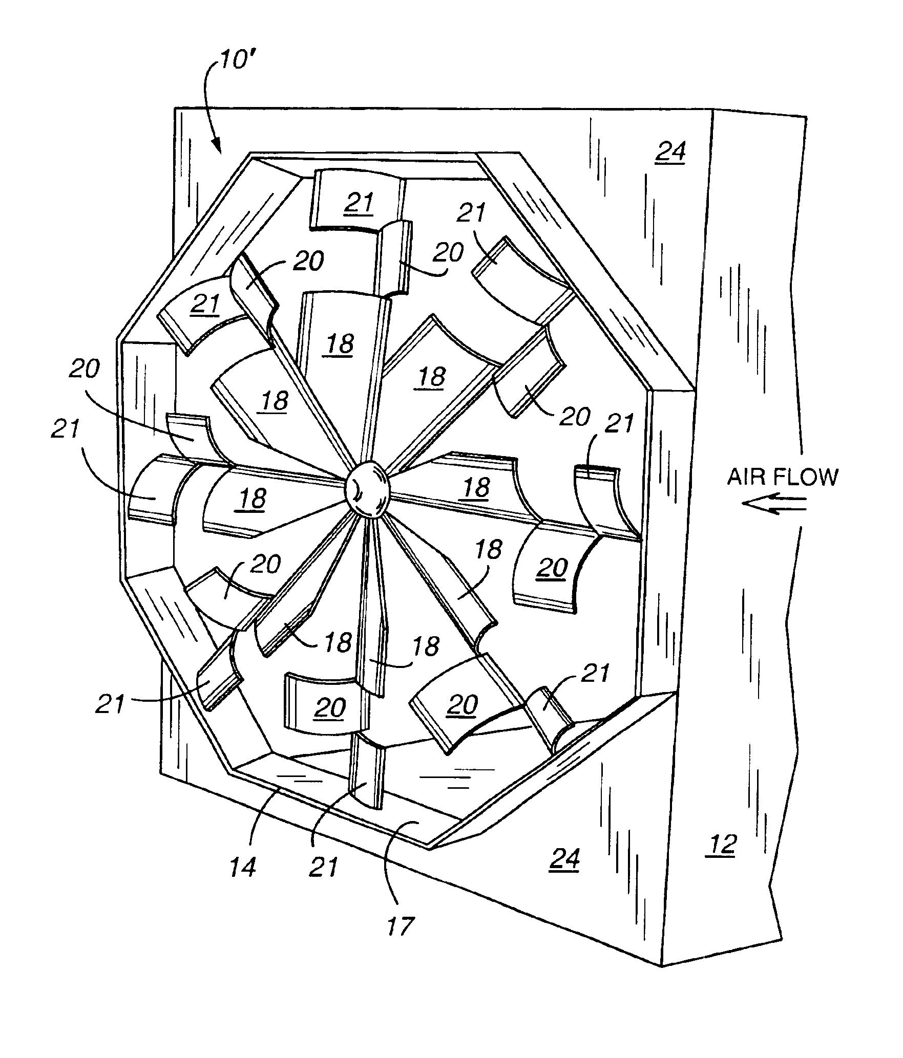
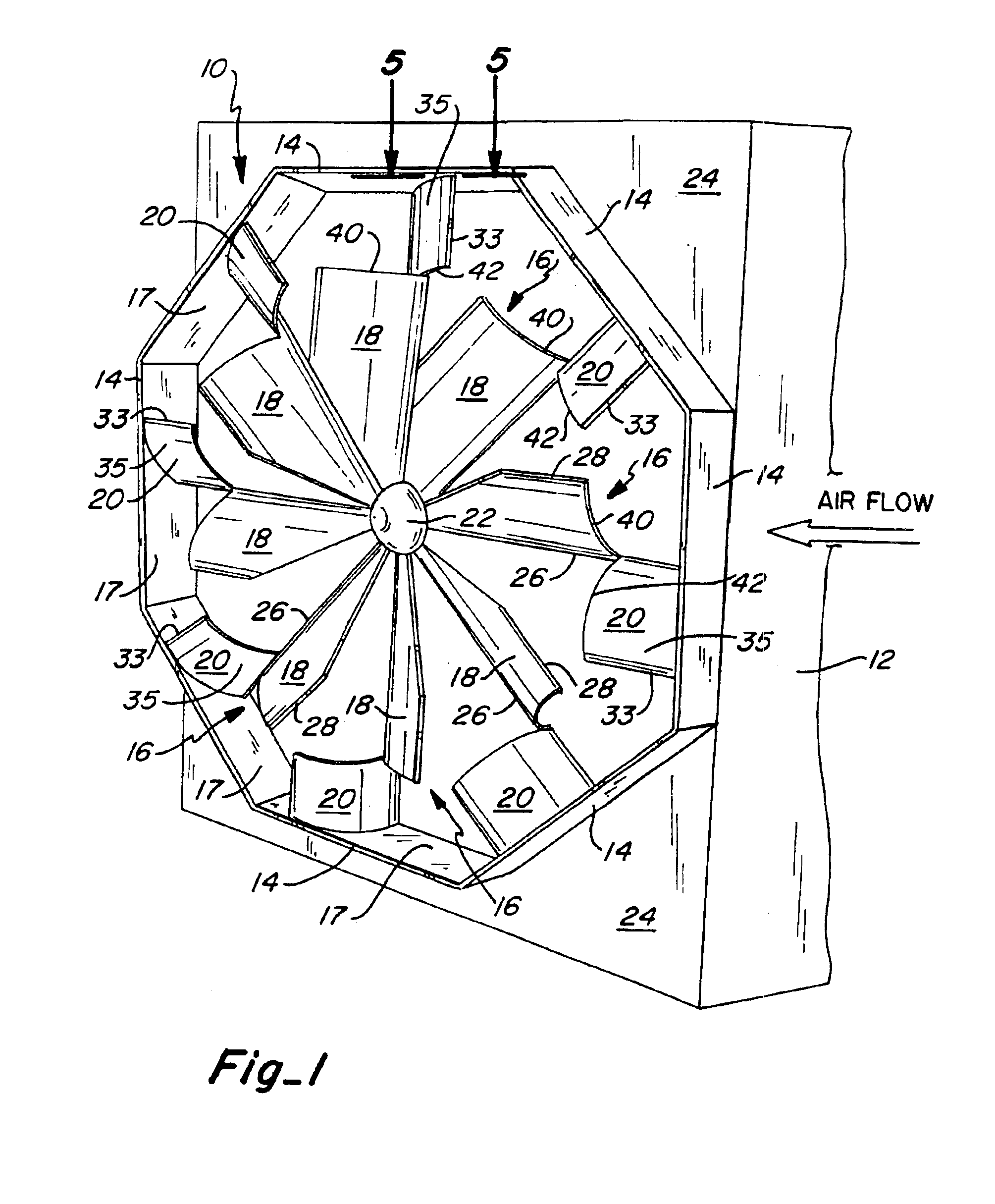
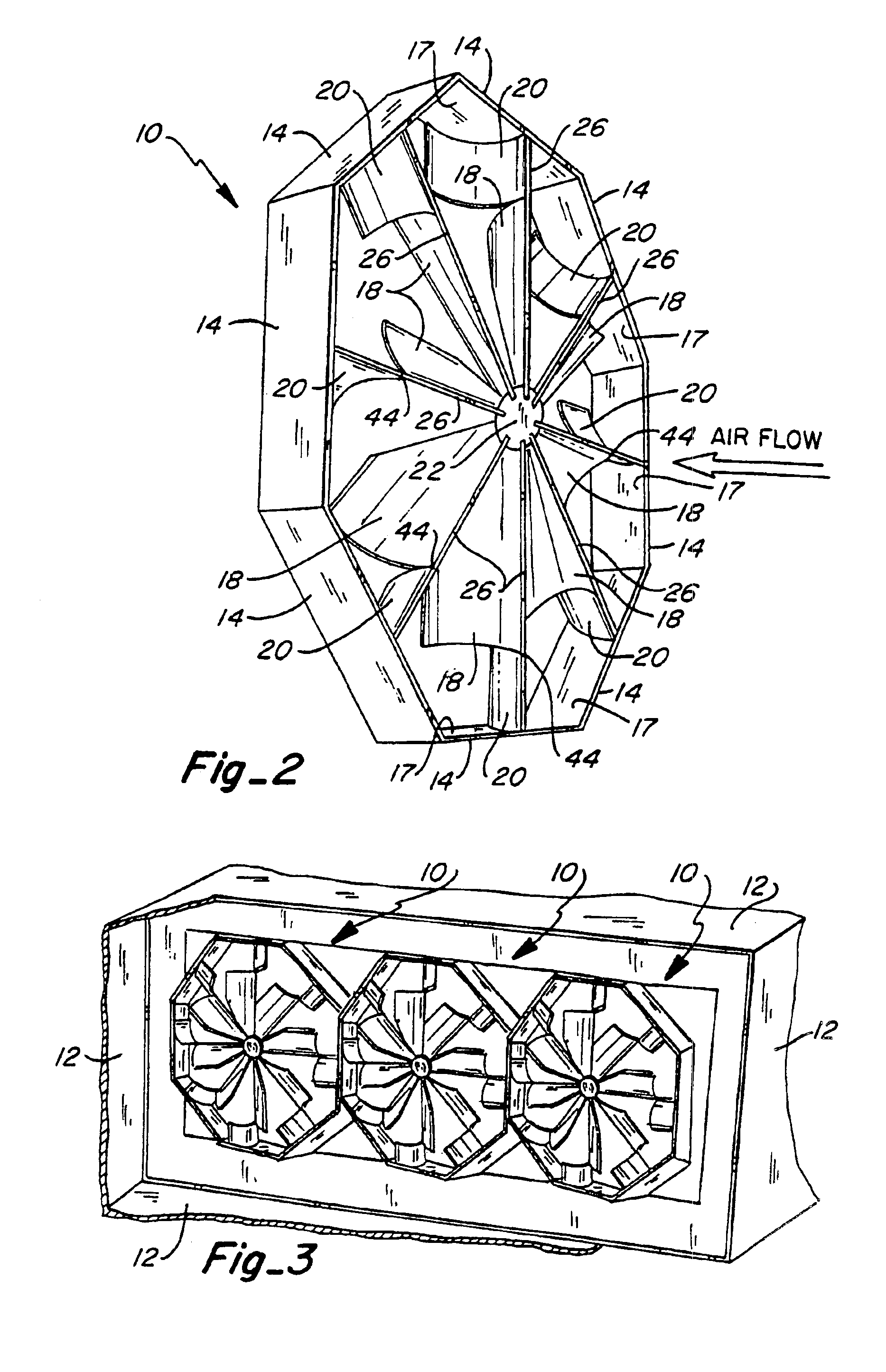
FIGS. 1 and 2 illustrate the static air mixing apparatus of the current invention, shown as mixing apparatus 10. The apparatus includes an enclosure 14 which is mounted within and partially traverses a duct 12. The air mixing apparatus 10 is a static device which has no moving parts. Preferably, the enclosure 14 has an octagonal shape including eight corresponding rectangular panel portions joined in an end-to-end relation to one another. The enclosure 14 carries a plurality of radially extending vanes or blades 16 which diverge away from a center of the enclosure, and terminate at their outer distal ends at the inner wall surface 17 of the enclosure 14. Preferably, the vanes 16 are uniformly spaced from one another, and each of the vanes includes an inner section 18 and a corresponding outer section 20 which shares a common leading edge with the inner section 18. The inner sections 18 of the vanes are preferably curved in the same downstream direction to impart either a clockwise o...


PUM


Abstract

A fixed blade air mixing apparatus includes a plurality of radially extending vanes which extend away from a common center and terminate at their outer ends within a polygonal shaped enclosure. The plurality of vanes may include an inner section which is curved or pitched in one direction, and an outer section which is curved or pitched in a second direction away from the inner section, the inner and outer sections sharing a common leading edge. In another embodiment, the vanes extend straight without a curvature. The apparatus is intended for use in eliminating stratification of airstreams of different temperatures flowing through a common passage, for example, in heating, air conditioning, or other ventilating ducts. The vanes are designed to establish downstream turbulence of the airstreams passing therethrough which produces optimum mixing effectiveness and a uniform velocity profile of the air downstream of the mixing apparatus with a minimum pressure drop as the air flows through the apparatus.

Description

TECHNICAL FIELDThis invention relates to heating, ventilating and air conditioning systems, and more particularly, to an air mixing apparatus of simplified construction which still achieves adequate mixing efficiency while maintaining a uniform velocity profile and minimum pressure drop.BACKGROUND OF THE INVENTIONAir streams which are introduced at different temperature levels through a common duct in heating, ventilating and air conditioning (HVAC) systems require intimate mixing in the duct in order to avoid undesirable stratification of air prior to passage of the airstream into a room airspace to be heated or cooled. Failure to achieve intimate mixing in the duct ultimately results in inefficient heating and cooling of the room air space and therefore can significantly affect the cost in operating and maintaining an HVAC system.A number of prior art references exist which disclose various static air mixing devices. The assignee of the current invention is the owner of a number o...

Claims


Application Information

Patent Timeline
Patent Type & Authority Patents(United States)
IPC IPC(8): F24F13/04
CPCF24F13/04
Inventor ROBINSON, KEITH D.
Owner BLENDER PROD
Learn More