
Archery arrow rotation prior to separation from bow

a technology of arrows and bows, applied in the field of archery bows or crossbows, can solve the problems of unnecessary drag on the rotating arrow, the arrow is more prone to deviating from the intended flight path, and the energy required to rotate the arrow shaft due to prior art arrow rotor drag robs valuable forward velocity through all phases of flight, so as to increase the impact energy, the effect of simple bow tuning

Inactive Publication Date: 2005-04-12
HOLLARS ANTHONY SCOTT +1
View PDF7 Cites 10 Cited by
  • Summary
  • Abstract
  • Description
  • Claims
  • Application Information

AI Technical Summary

Benefits of technology

It is a further object of the present invention to eliminate fletching completely. Utilizing the arrow rotation device for archery bows, test firings have been predictably accurate utilizing no fletching. Additional benefits realized utilizing no fletching are increased flight distances and flatter trajectories. Another advantage of the present invention is increased downrange velocity resulting in increased impact energy.
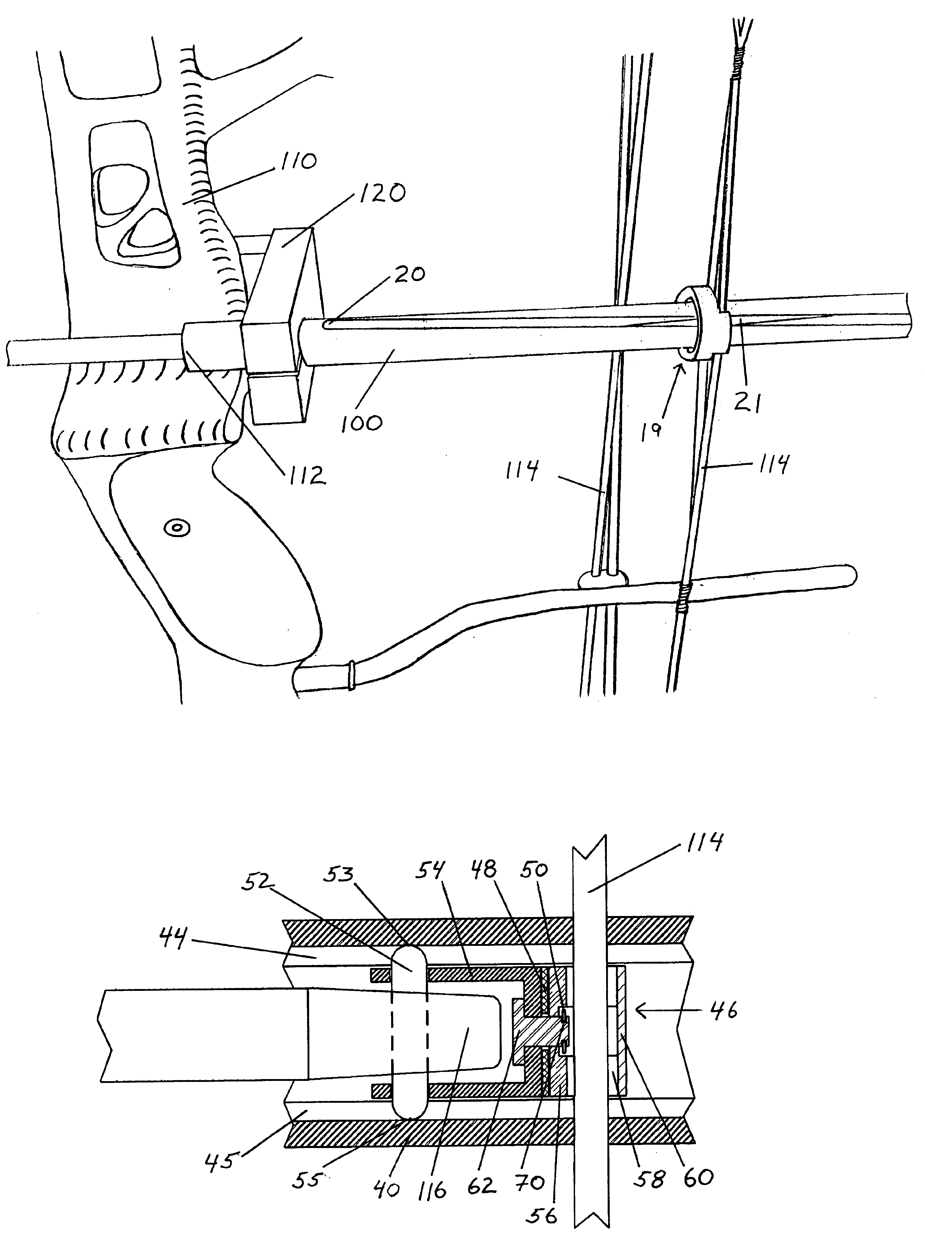
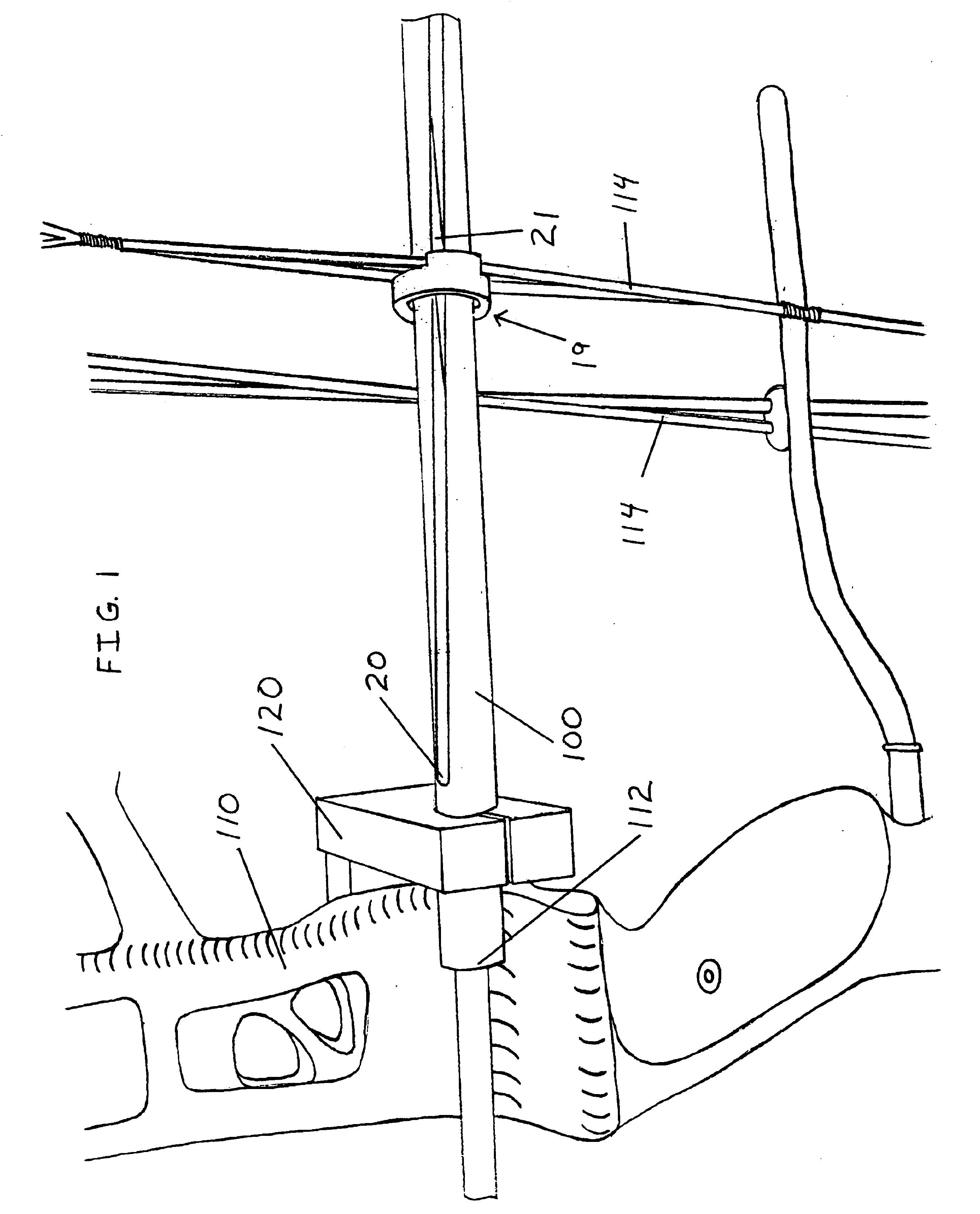
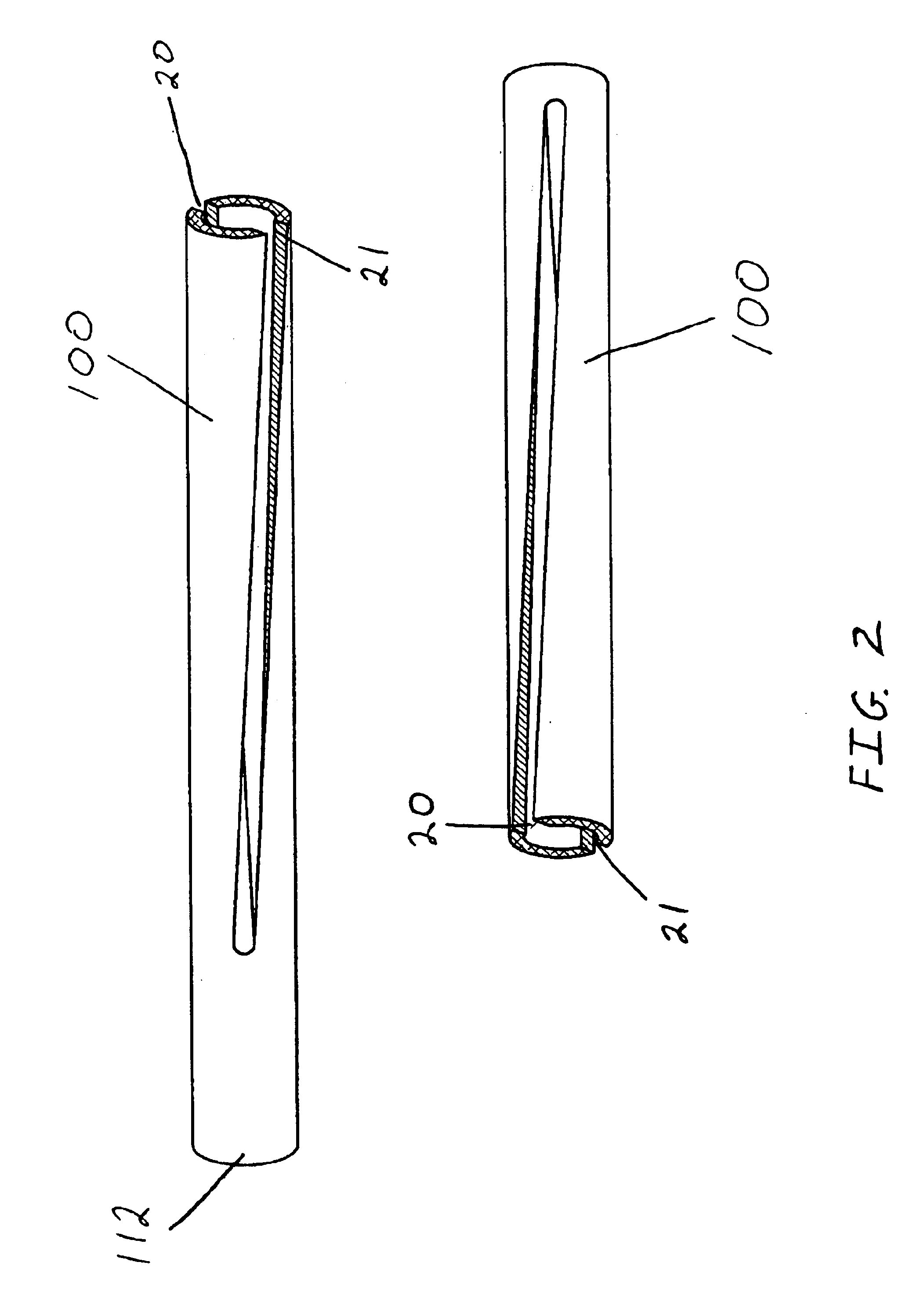
In one embodiment of the present invention, a diametrically opposed helically slotted spin tube mounts rigidly to the bow oriented such that an arrow fits inside the tube. Following the outer diameter of the spin tube is a nock drive collar or collar. The function of the nock drive collar is to ride on the outer diameter of the spin tube. Additionally, the nock drive collar captures the bowstring. Contained within the collar is a nock pin. The nock pin freely radially rotates while remaining captured within the nock drive collar. Pin rotation is urged as the collar translates along the spin tube. The nock pin follows the diametrically opposed, helical slots. By having an arrow nock in contact with the rotating nock pin contained within the nock drive collar installed on the spin tube, the arrow rotates in reverse upon draw and more importantly, upon release. Bow tuning becomes simpler because the guide tube now determines bowstring nock point. Mounting is possible with existing archery equipment incurring no permanent modifications. As an example, a tube bracket mounts to the same location on a riser as an arrow rest. This will become apparent from a consideration of the drawings and ensuing description. Alternatively, a riser can incorporate a spin-tube in an integrated, designed-in fashion.
In another embodiment of the present invention, a tube mounts to the riser of a bow. The tube has an inner diameter that allows clearance for an arrow. Diametrically opposed slots run along the major axis of the tube, oriented at the top most and bottom most parts of the tube. A bowstring runs through the opposed slots. On the inside of the tube are helical grooves or ridges that resemble rifling on a firearm barrel. An internal nock drive collar runs along the inside of the tube and attaches to the bowstring. Part of the internal nock drive collar contacts the bowstring and purely translates within the slotted tube upon bowstring draw and release. Another part of the nock drive collar that has the nock drive pin, translates in conjunction with the rest of the collar but rotation also occurs. Rotation is urged by part of the internal nock drive collar mechanically following the tube internal grooves or ridges. The arrow nock connects with the rotating component of the nock drive collar effectively rotating the arrow upon release (and draw) by an archer. Additionally, bow tuning becomes simpler because the guide tube now determines bowstring nock point.
In another embodiment of the present invention, mechanical arrow rotation is urged through physical contact with a plurality of deformable contact wheel arrow shaft rotators. As an archer releases the bowstring and arrow accelerates through the bow, the contact wheels roll about their axles while in contact with the arrow shaft. Additionally, inherent slip between the contact wheels and arrow shaft is likely to occur. Intentional contact wheel angular misalignment allows contact wheels to rotate in relation to a translating arrow shaft, yet slightly grip the arrow shaft to induce rotation as well. The contacting wheels can be of varied durometer materials or a combination of durometers within the same wheel. Angular adjustability for the contact wheels needs to be flexible. Flexibility includes differing from the arrow longitudinal axis as well as allowing for variances in arrow shaft diameters. Spring-loaded wheels are one preferred method to ease arrow insertion and allow tuning flexibility.
In a further embodiment, the present invention modifies an arrow shaft to accomplish the same result. Straight or spiral grooves running along the arrow major axis pass through or along contacting guides mechanically inducing arrow shaft rotation about the longitudinal axis as an archer releases the bowstring. Alternatively, straight or spiral ridges running along the arrow major axis pass through or along contacting guides. Either a freely rotating nock drive collar attaches at the nock point of the bowstring or the arrow nock must freely rotate in relationship to the arrow shaft because the nock cannot rotate while engaged with the bowstring. An additional advantage to helically oriented grooves or ridges running at least part way along an arrow longitudinal axis allow aerodynamic benefits. The double duty of the helical design initially gets the arrow rotating prior to free flight by following the contacting guides and second, aerodynamically performs the same function as fletching once in free flight to maintain the rotation.

Problems solved by technology

The negative effects of zero initial rotational velocity about the longitudinal spin axis upon launch make an arrow more prone to deviate from the intended flight path.
The energy required to rotationally accelerate the arrow shaft caused by prior art fletching drag robs valuable forward velocity through all phases of flight.
Once the arrow is sufficiently rotating at a latter position in the flight path, substantial fletching now causes unnecessary drag on the rotating arrow.
However, due to the decreased clearance between archery vanes, the archery vanes interfere with an arrow rest of a bow, for example as an archer launches the arrow.
This interference causes the arrow to change direction when fired from the bow or wobble during flight, resulting in decreased accuracy and flight distance.
Further, because of a required offset position, arrows having helically oriented archery vanes are difficult to manufacture and create greater aerodynamic drag during flight.
However, the convex surface produces only a small amount of fluid displacement and relatively little rotation of the arrow during flight.
Thus, these conventional archery vanes do not provide the desired rotation and stability to the arrow.
The smallest deviation from intended flight path at the beginning of flight continues to grow in error as flight distance and flight time increase.
Bullets from guns leave the barrel already spinning.
No known prior art archery bows launch a pre-spinning arrow.
The disadvantage of waiting for an arrow to be moving through a fluid to create the desired rotational forces simply allows more time for introduced influential errors in the first moments of free flight.

Method used


Image

  • Archery arrow rotation prior to separation from bow
  • Archery arrow rotation prior to separation from bow
  • Archery arrow rotation prior to separation from bow

Examples


Embodiment Construction

The arrow rotation device of the present invention substantially reduces the described disadvantages of prior art arrow rotation systems by inducing a rotation on the arrow shaft prior to leaving the bow and entering free flight. Accuracy improves because unwanted influential forces can be overwhelmed by beneficial conservation of angular momentum forces by causing the arrow to rotate before leaving the bow. Because fletching can be eliminated or downsized, other resultant advantages follow. Improved trajectory due to reduced drag, reduced influence due to cross winds, better down range velocity, and impact force, are among the more substantial improvements.

FIG. 1 is a perspective view of the diametrically opposed, helically slotted spin tube arrow rotation device for archery bow. By utilizing the existing standardized arrow rest mounting point commonly located on the riser of bows, the arrow rotation device is easily adaptable to any existing bow. A spin tube-to-riser mount 120, ri...


PUM


Abstract

The arrow rotation device of the present invention substantially reduces the described disadvantages of prior art arrow rotation systems by inducing a rotation on the arrow shaft prior to leaving the bow and entering free flight. It is an object of the present invention to provide a means for inducing a rotational velocity about the longitudinal axis of an arrow as it travels through the bow over the releasing range. It is another object of this invention to provide an arrow rotating system that can be used with existing archery bows with minimal modifications or available as a factory option (OE). It is a further object of the present invention to provide a means for mechanically inducing a rotational velocity about the longitudinal axis of an arrow through a constant or a variable rotational acceleration to achieve a desired rotational velocity prior to separation of an arrow from the bow.

Description

FEDERALLY SPONSORED RESEARCHNot ApplicableSEQUENCE LISTING OR PROGRAMNot ApplicableTECHNICAL FIELDThis invention relates to archery bows or crossbows, particularly a mechanical means to generate arrow shaft rotation about the longitudinal axis prior to leaving the bow upon bowstring release by an archer, thus providing increased stability, distance and improved flight accuracy of the arrow.BACKGROUND ARTConventional archery methods of inducing arrow shaft rotation about the longitudinal spin axis primarily use variations of fletching or vanes. Launching an arrow into free flight upon release of the bowstring, air passing across fletching mounted with an angular offset to the longitudinal axis of the arrow, induces a torque about the longitudinal axis of an arrow. The net result is arrow rotation only after the arrow has traveled some distance. Features common to conventional methods require the arrow to be moving through a fluid to create the desired rotational forces. During the fi...

Claims


Application Information

Patent Timeline
IPC IPC(8): F41B5/22F41B5/00F42B10/26
CPCF42B10/26F41B5/143
Inventor HOLLARS, ANTHONY SCOTTEDWARDS, JON MARC
Owner HOLLARS ANTHONY SCOTT
Learn More