
Xerographic printing system with magnetic seal between development and transfer

Inactive Publication Date: 2005-04-05
XEROX CORP
View PDF16 Cites 7 Cited by
  • Summary
  • Abstract
  • Description
  • Claims
  • Application Information

AI Technical Summary

Problems solved by technology

However, in each of those products, the photoreceptor and sleeve of the developer roll moved in the same direction through the development zone, and therefore a set of airflows such as described below would not be set up by the motion of the photoreceptor and sleeve.

Method used


Image

  • Xerographic printing system with magnetic seal between development and transfer
  • Xerographic printing system with magnetic seal between development and transfer
  • Xerographic printing system with magnetic seal between development and transfer

Examples


Embodiment Construction

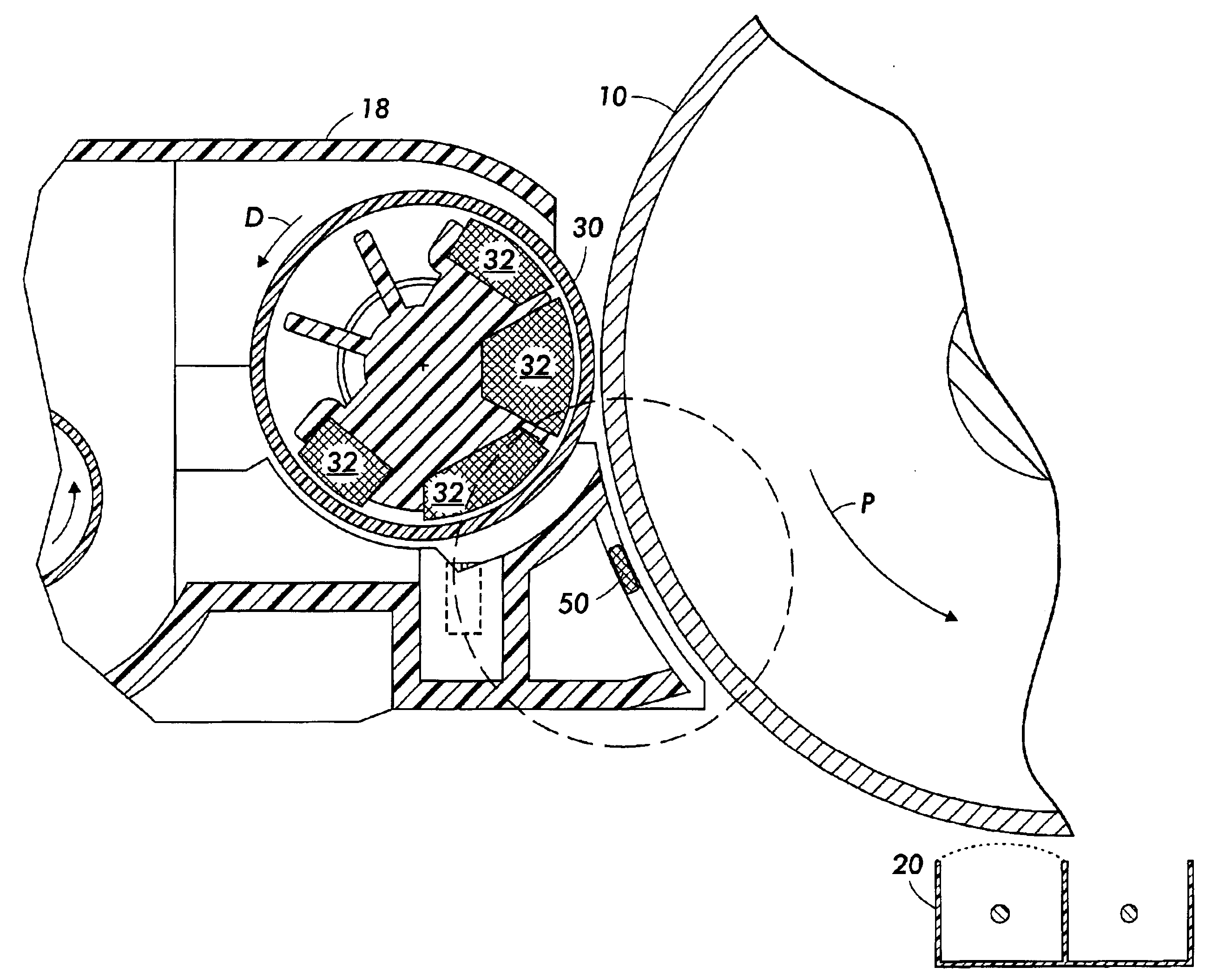
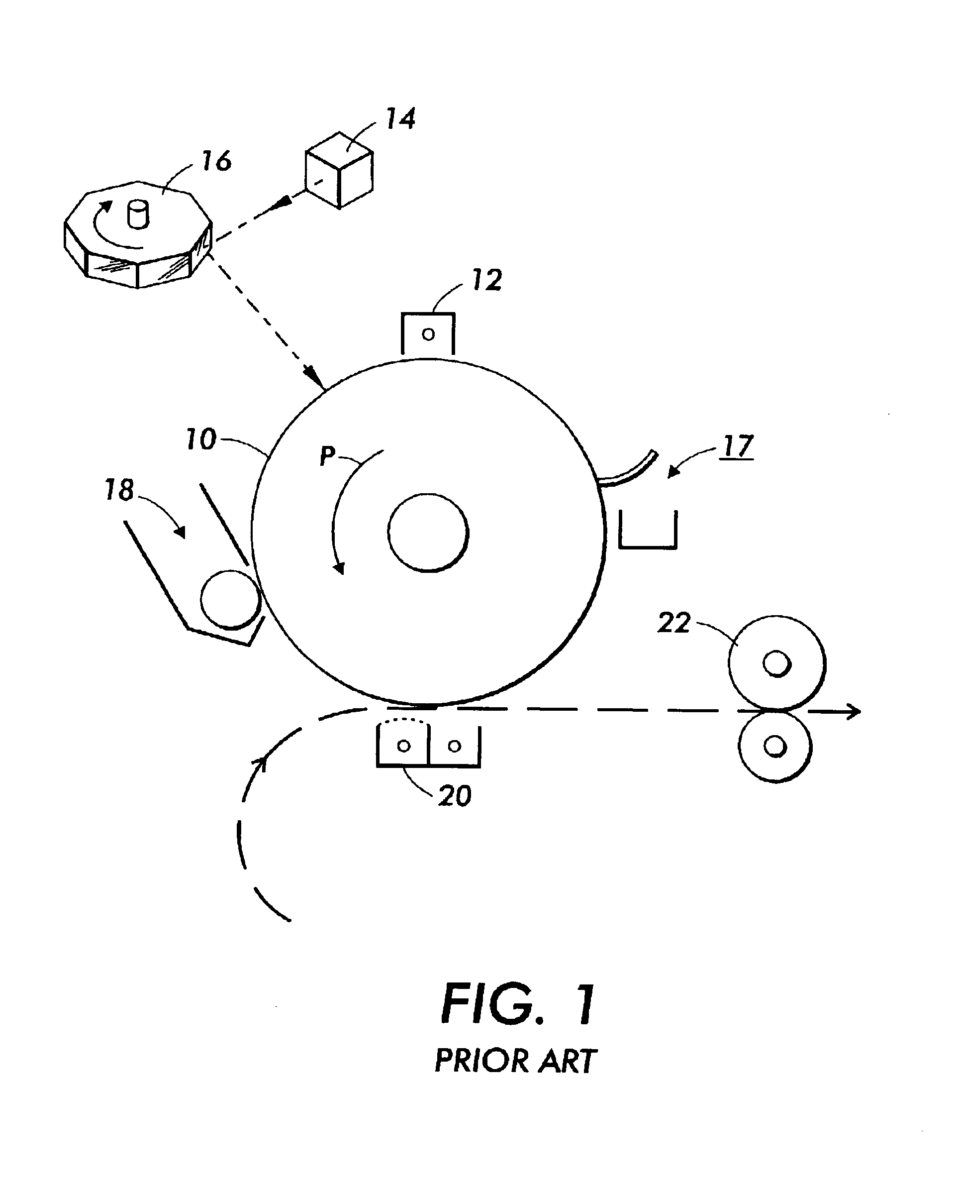
FIG. 1 shows the basic elements by which a electrostatographic or xerographic printer, such as a copier or a “laser printer,” creates a dry-toner image on plain paper. There is provided in the printer a charge receptor such as photoreceptor 10, which may be in the form of a belt or drum, and which defines a charge-retentive surface for forming electrostatic images thereon. The photoreceptor 10 is caused to rotate through process direction P.

The first step in the process is the general charging of the relevant photoreceptor surface. This initial charging is performed by a charge source such as a “scorotron,” indicated as 12. The scorotron 12 typically includes an ion-generating structure, such as a hot wire, to impart an electrostatic charge on the surface of the photoreceptor 10 moving past it. The charged portions of the photoreceptor 10 are then selectively discharged in a configuration corresponding to the desired image to be printed, by a raster output scanner or ROS, which gene...


PUM


Abstract

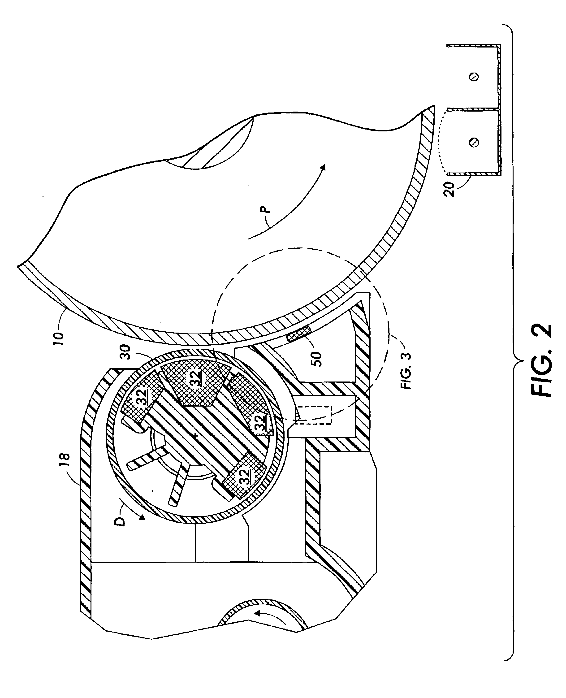
In a xerographic development apparatus using a magnetic brush formed from magnetic carrier particles, a magnetic strip disposed downstream of the development zone along the direction of motion of the photoreceptor retains a separate, small brush of carrier particles near the photoreceptor. The brush acts as a barrier separating a flow of “dirty” air (laden with airborne toner particles) upstream of the strip, and a flow of clean air downstream of the strip.

Description

TECHNICAL FIELDThe present invention relates to electrostatographic or xerographic printing systems.BACKGROUNDIn the well-known process of electrostatographic printing, the most common type of which is known as “xerography,” a charge retentive surface, typically known as a photoreceptor, is electrostatically charged, and then exposed to a light pattern of an original image to selectively discharge the surface in accordance therewith. The resulting pattern of charged and discharged areas on the photoreceptor form an electrostatic charge pattern, known as a latent image, conforming to the original image. The latent image is developed by contacting it with a finally divided electrostatically attractable powder known as “toner.” Toner is held on the image areas by the electrostatic charge on the photoreceptor surface. Thus, a toner image is produced in conformity with a light image of the original being reproduced. The toner image may then be transferred to a substrate, such as paper, a...

Claims


Application Information

Patent Timeline
Patent Type & Authority Patents(United States)
IPC IPC(8): G03G15/09G03G15/08
CPCG03G15/0942
Inventor MASHAM, ROGER D.
Owner XEROX CORP
Learn More