Method and apparatus for measuring photoelectric conversion characteristics

a technology of photoelectric conversion and measurement method, which is applied in the direction of individual semiconductor device testing, photovoltaic monitoring, instruments, etc., can solve the problems of unstable manufacturing yield, inability to guarantee the maximum power of a photoelectric conversion device to be delivered, and inevitably decrease the manufacturing yield, so as to achieve accurate measurement of photoelectric conversion characteristics and low cost

Inactive Publication Date: 2005-04-05
CANON KK
View PDF7 Cites 18 Cited by
  • Summary
  • Abstract
  • Description
  • Claims
  • Application Information

AI Technical Summary

Benefits of technology

The present invention has been made to solve the above-described problems individually or altogether, and has as its object to accurately measure photoelectric conversion characteristics at low cost without being affected by the light-receiving area and form of the object to be measured, measurement position, and measurement light.

Problems solved by technology

However, the maximum power of a photoelectric conversion device to be delivered cannot be guaranteed unless the output characteristics can be accurately measured.
In addition, if an output characteristics measurement error is large, and the measurement error changes depending on the state of the measuring apparatus, the inspection threshold value varies even for photoelectric conversion devices with the same quality, resulting in unstable manufacturing yield.
Furthermore, if the inspection threshold value includes a measurement error value to guarantee the quality of photoelectric conversion devices to be delivered, the manufacturing yield inevitably decreases.
If the output of a stacked photoelectric conversion device cannot be accurately expected, no expected system characteristic can be obtained or the system efficiency degrades in building a system using the stacked photoelectric conversion device.
However, it is very difficult to accurately measure the output characteristics of a stacked photoelectric conversion device.
However, of these standard test conditions, the spectrum of standard sunlight can hardly be obtained even when outdoor sunlight is used.
This is because the standard sunlight is obtained only under limited meteorological conditions.
It is impossible to obtain the spectrum of standard sunlight using a pseudo sunlight source indoors.
However, in a stacked solar cell, the spectrum affects not only the short-circuit current but also the fill factor and open-circuit voltage, as described above, and the output characteristics cannot be accurately measured by the above measuring method.
However, due to the following reasons, it is very difficult to manufacture a spectrum adjustable solar simulator having an area more than 400 cm2.(i) Since a plurality of light components having different spectra are synthesized, the positional variations in spectrum of the synthesized light and in irradiance become large.
The larger the irradiation area is, the more serious these variations become.(ii) Since the spectrum of partial light from the light source is used, the light intensity tends to be low.
When the irradiation area becomes large, it is hard to obtain a irradiance of the standard test condition of 1,000 W / m2.(iii) The structure becomes complex, and the manufacturing cost largely increases as compared to a normal solar simulator using a single light source.(iv) Adjustment of the solar simulator with variable spectrum is cumbersome, and its control requires skill.
However, due to the above reasons, the light-receiving area of the solar cell to be measured is limited to the minimal area of laboratory level, and it is hard to measure a cell, module, or array having an area more than 400 cm2.
Even when a measuring apparatus for the multi-source method can be manufactured, the cost is very high.
In addition, the multi-source method cannot be used for measurement using outdoor sunlight.

Method used


Image

  • Method and apparatus for measuring photoelectric conversion characteristics
  • Method and apparatus for measuring photoelectric conversion characteristics
  • Method and apparatus for measuring photoelectric conversion characteristics

Examples


example 1

The output characteristics of a triple solar cell having a three-layered structure including a top cell with a pin junction using amorphous silicon (to be referred to as “a-Si” hereinafter) for an i-layer, a middle cell with a pin junction using amorphous silicon germanium (to be referred to as “a-SiGe” hereinafter) for an i-layer, and a bottom cell with a pin junction using a-SiGe for an i-layer were measured by a known pulse-light-type solar simulator using a xenon lamp as a light source.

The triple solar cell had a size of about 1 cm×1 cm formed on a single stainless steel substrate and was in a single unit state before cells were connected in series or in parallel. No surface protective layer was formed. The solar simulator had an effective irradiation area of about 10 cm×10 cm. The time variation ratio of the irradiance was ±1% or less, and the positional variation in irradiance was ±2% or less.

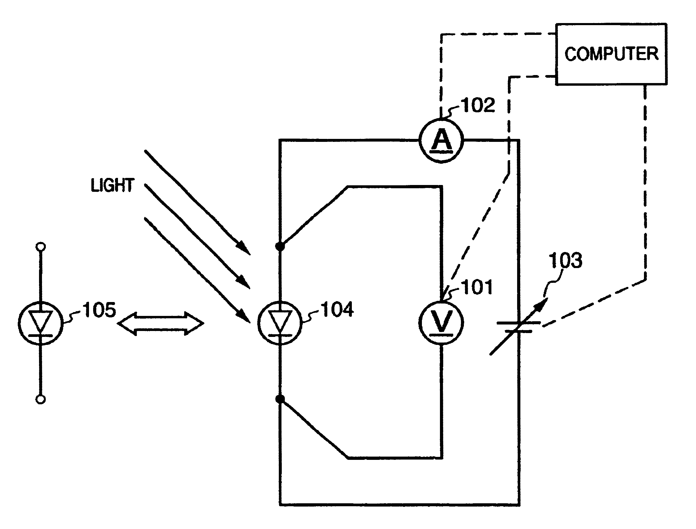
As a power supply 103, a known bipolar power supply was used. The voltage was swept b...

example 2

The same sample cell as in Example 1 was measured in accordance with the same procedure as in Example 1. FIG. 9 shows results obtained by correcting the measurement results not by equation (9) but by equation (10). FIG. 10 shows results obtained by dividing the results of Example 2 before and after correction shown in FIG. 9 by the values shown in FIG. 7 and representing the increase / decrease in each value by percentage. As is apparent from the results shown in FIG. 10, even with the measuring method of this embodiment using equation (10), accurate measurement results almost the same as those by the multi-source method can be obtained.

example 3

The output characteristics of a double solar cell having a two-layered structure including a top cell with a pin junction using a-Si for an i-layer and a bottom cell with a pin junction using micro-crystallite silicon (to be referred to as “μc-Si” hereinafter) for an i-layer were measured by a known solar simulator using a xenon lamp as a light source.

The double solar cell was a submodule which had a size of about 25 cm×18 cm formed on a single stainless steel substrate and was in a single unit state before submodules were connected in series or in parallel. No surface protective layer was formed. The solar simulator had an effective irradiation area of about 130 cm×80 cm. The positional variation in irradiance was ±3% or less, and the positional variation in irradiance within the area of the submodule was ±1.5% or less.

As a power supply 103, a known electronic load was used. The voltage was swept by a personal computer. As voltage and current detectors 101 and 102, a combination of...


PUM


Abstract

For the multi-source method suitable to measure the photoelectric conversion characteristics of a stacked solar cell, the light-receiving area of the solar cell to be measured is limited to the minimal area of laboratory level, and it is hard to measure a cell, module, or array having an area more than 400 cm2. To cope with this problem, the irradiance of irradiation light is measured or adjusted, the current vs. voltage characteristic of a reference cell is measured, and the current vs. voltage characteristic of a sample cell is measured. Next, the current vs. voltage characteristic of the reference cell in standard test conditions is compared with the measurement result of the current vs. voltage characteristic of the reference cell, thereby obtaining a shift of the measurement result from the standard test condition on the basis of the shift of the irradiation light from the standard test condition. On the basis of the obtained shift of the measurement result, the measurement result of the current vs. voltage characteristic of the sample cell is corrected, and the photoelectric conversion characteristics of the sample cell are obtained.

Description

FIELD OF THE INVENTIONThe present invention relates to a method and apparatus for measuring photoelectric conversion characteristics and, more particularly, to a method and apparatus for measuring the photoelectric conversion characteristics of a photoelectric conversion device such as a solar cell, photodiode, photosensor, or electrophotographic photosensitive body and, especially, a stacked photoelectric conversion device.BACKGROUND OF THE INVENTIONIn a stacked photoelectric conversion device in which a plurality of photoelectric conversion elements with different spectral responses are stacked, long-wavelength light that cannot be completely absorbed by the upper photoelectric conversion element on the light incident side is absorbed by the lower photoelectric conversion element, thereby increasing the output or sensitivity. Hence, such stacked photoelectric conversion devices have been extensively developed.It is very important to accurately measure the output characteristics of...

Claims


Application Information

Patent Timeline
Patent Type & Authority Patents(United States)
IPC IPC(8): G01R31/26G01R31/308H02S50/10
CPCH02S50/10G01R31/308Y02E10/50
Inventor MATSUYAMA, JINSHO
Owner CANON KK
Why Eureka
Try Eureka