
Electrically conductive thermoplastic elastomer composite

a thermoplastic elastomer and composite technology, applied in the direction of non-metal conductors, cellulosic plastic layered products, conductors, etc., can solve the problems of increasing the volume fraction, and increasing the cost of production, so as to improve the electrical conductivity of the elastomer, the elastomer composite of the invention is low, and the electrical conductivity is good

Inactive Publication Date: 2005-04-05
PREMIX OY
View PDF3 Cites 7 Cited by
  • Summary
  • Abstract
  • Description
  • Claims
  • Application Information

AI Technical Summary

Benefits of technology

"The present invention provides an electrically conductive thermoplastic elastomer composite with better electrical conductivity and low effect of compression on the electrical conductivity. The composite is characterized in that the electrically conductive particles are at least partly coated with a self-assembled monomolecular layer. The monomolecular layer acts as a passivation layer and can be attached with electrically conductive polymer molecules or neutral molecular wires. The electrical conductivity of the elastomer is better than previously and the melt viscosity is low, allowing it to be used for the manufacture of high-quality products having complicated shapes."

Problems solved by technology

Crosslinking requires much energy and time, and special crosslinking means, making the manufacture of the products slow and the production costs high.
However, increasing the volume fraction deteriorates (among other things) the mechanical properties, workability and surface quality of an elastomer composite.
Furthermore, the price of the material often increases significantly.
Consequently, the volume fraction cannot be increased limitlessly to increase electrical conductivity.
However, a significant problem is associated with known electrically conductive thermoplastic elastomer composites: when subjected to compressive force, the resistivity of the composite rises greatly.
Often in practical applications, some compression is directed to products made from said material, e.g. seals, and thus the problem is extremely common and harmful.

Method used


Image

  • Electrically conductive thermoplastic elastomer composite
  • Electrically conductive thermoplastic elastomer composite
  • Electrically conductive thermoplastic elastomer composite

Examples


example 1

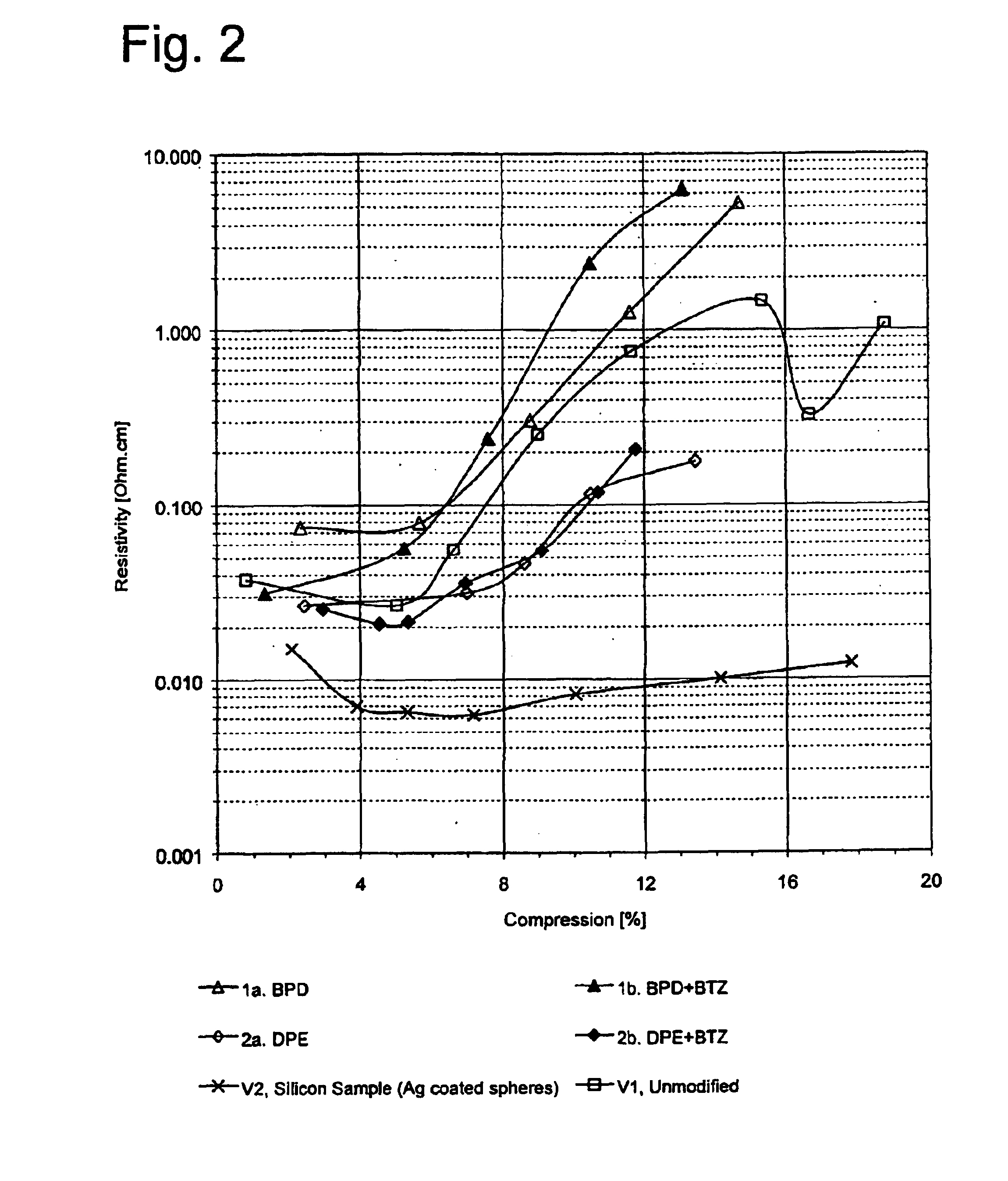
The direct coating of molecular wires was studied by self-assembly on the surface of filler particles. As the molecular wire, the effect of BPD and DPE (Sagara et al, Langmuir 6, 254-262) on the resistivity values of the elastomer test specimens was tested. Electrically conductive elastomers of the invention were prepared, and the resistivity values of the test specimens made from them were measured. The effect of BTZ was also studied, since BTZ is known to be strongly adsorbed onto silver surfaces (S. Kapoor, Langmuir 14 (1998) 1021-1025, N. Shibata & S. Suzuki, J. Pat. 3158230, 1991).

Coating Filler Particles

Different compound combinations were diluted in 250 ml organic solvent in accordance with Table 1. The solution was added to 60 grams of silver-coated fibreglass particles. The slurry obtained was mixed for at least 1 hour at room temperature, and the slurry was then filtered in a Buchner funnel. The particles were rinsed three times carefully with a solvent, and then the parti...

example 2

In example 2, the effect of octadecylmercaptan ODM and different aromatic compounds on the resistivity values of prepared elastomer test specimens was studied. The fibrous filler particles were coated as in Example 1. The elastomer was prepared and the resistivity of the elastomer composite measured as in Example 1. The compounds used and their amounts are given in Table II.

TABLE IICompounds andSolvent (adsorptionSpecimenamounts thereof / 250phase / washingNo.ml solvent and 60 g fillerphase)3a1 g ODMToluene / toluene3b1 g ODM + 0.24 g QT)1toluene / acetone4a1 g ODMchloroform / chloroform4b1 g ODM + 0.5 g BTZchloroform / chloroform4c1 g ODM + 0.24 g QT)2chloroform / chloroform4d1 g ODM + 0.24 g DPHTchloroform / chloroform  5a)o1 g ODM + 0.24 g DPHTchloroform / chloroform)1QT was not completely dissolved, )2the solution had to be filtered, )osilver-coated spheres

Results

FIG. 3 shows the resistivities of the elastomer composites according to Example 2. The resistivities of elastomer composites filled wi...

example 3

Example 3 deals with the effect of octadecylmercaptan ODM, dodecylmercaptan DDM and 1,6-diphenyl-1,3,5-hexatriene DPHT on the resistivity of elastomers. In these tests, coated spheres (50 percent by volume of the entire elastomer composite) are used instead of silver-coated fibres, and as solvent toluene, which has a better working safety than chloroform. Table III shows the compounds used. The filler particles were coated as in Examples 1 and 2, but the amount of substance was halved relative to the amount of filler. The elastomer was prepared and the resistivity of the elastomer composite was measured in the same way as in Examples 1 and 2.

TABLE IIICompounds andSpecimenthe amounts thereof / No.125 ml solvent and 60 g fillersolvent6a0.5 g ODMtoluene6b0.5 g ODM + 0.12 g DPHTtoluene7a0.5 g DDMtoluene7b0.5 g DDM + 0.12 g DPHTtoluene

Results

FIG. 4 shows the resistivity values of the different elastomer composites as a function of compression. Specimen 5a (Table II) gives a significantly l...


PUM

PropertyMeasurementUnit
temperatureaaaaaaaaaa
electrically conductiveaaaaaaaaaa
electricallyaaaaaaaaaa

Abstract

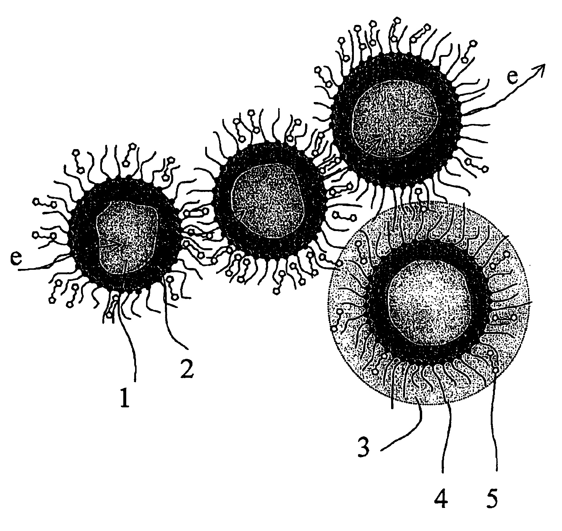
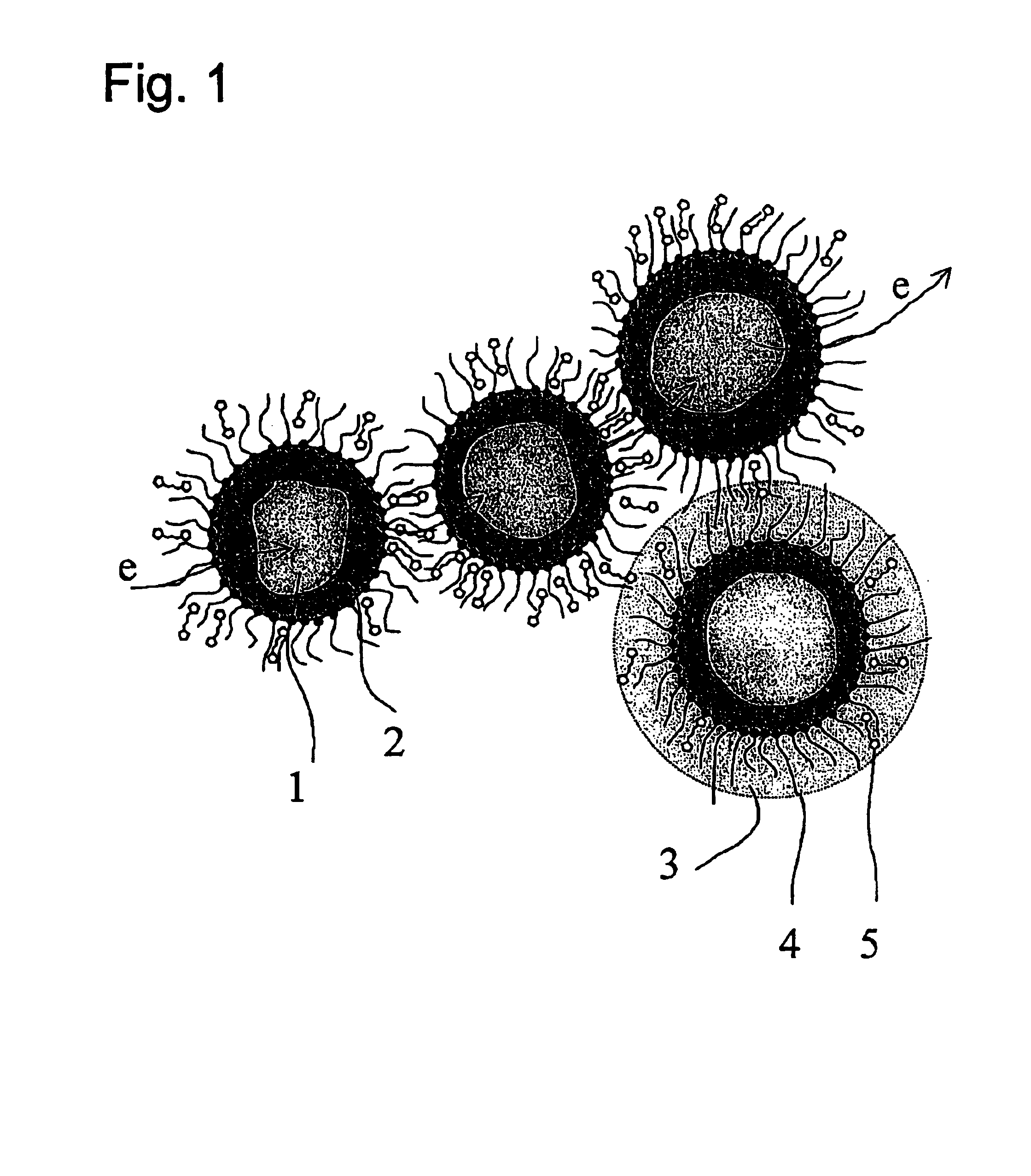
An electrically conductive thermoplastic elastomer composite comprising an elastomer matrix and particles coated with metal as an electrically conductive filler. The electrically conductive particles are at least partly coated with a self-assembled monomolecular layer. Alternatively, the coating may comprise molecular wires that settle between the self-assembled molecules. The resistivity of the thermoplastic elastomer of the invention is low and does not substantially increase by the action of compression.

Description

The invention relates to an electrically conductive thermoplastic elastomer composite comprising an elastomer matrix and metal-containing particles as an electrically conductive filler.BACKGROUND OF THE INVENTIONAs to their electrical properties, polymers and polymer mixtures are usually dielectrics. However, in some applications the polymer material preferably has some electrical conductivity. Such applications include antistatic packages, containers for inflammable substances and pipework, electrostatically painted fabricated shapes, and many other applications known per se. In addition, the increasing number of electronic devices has resulted in that, on the one hand, their electronics have to be protected from electromagnetic interference caused by other electronic devices and, on the other hand, the electronic interference caused by them on the outside has to be reduced. In other words, the devices are to be EMI shielded. Electrical conductivity is often achieved by mixing meta...

Claims


Application Information

Patent Timeline
Patent Type & Authority Patents(United States)
IPC IPC(8): C08K9/04C08K9/00H01B1/22
CPCB82Y30/00H01B1/22C08K9/04Y10T428/2998
Inventor ALBERS, MARTINKARTTUNEN, MIKKOVILKMAN, TAISTO
Owner PREMIX OY
Learn More