
Axial flux motor driven anode target for X-ray tube

a technology of axial flux motor and x-ray tube, which is applied in the direction of magnetic circuit rotating parts, magnetic circuit shape/form/construction, nuclear engineering, etc., can solve the problems of bearings exposed to a substantial thermal load, bearings experiencing excess mechanical load, and x-ray tube designers facing problems pertaining to excess static load and dynamic load experienced by bearings

Active Publication Date: 2005-03-29
GENERAL ELECTRIC CO
View PDF5 Cites 5 Cited by
  • Summary
  • Abstract
  • Description
  • Claims
  • Application Information

AI Technical Summary

Benefits of technology

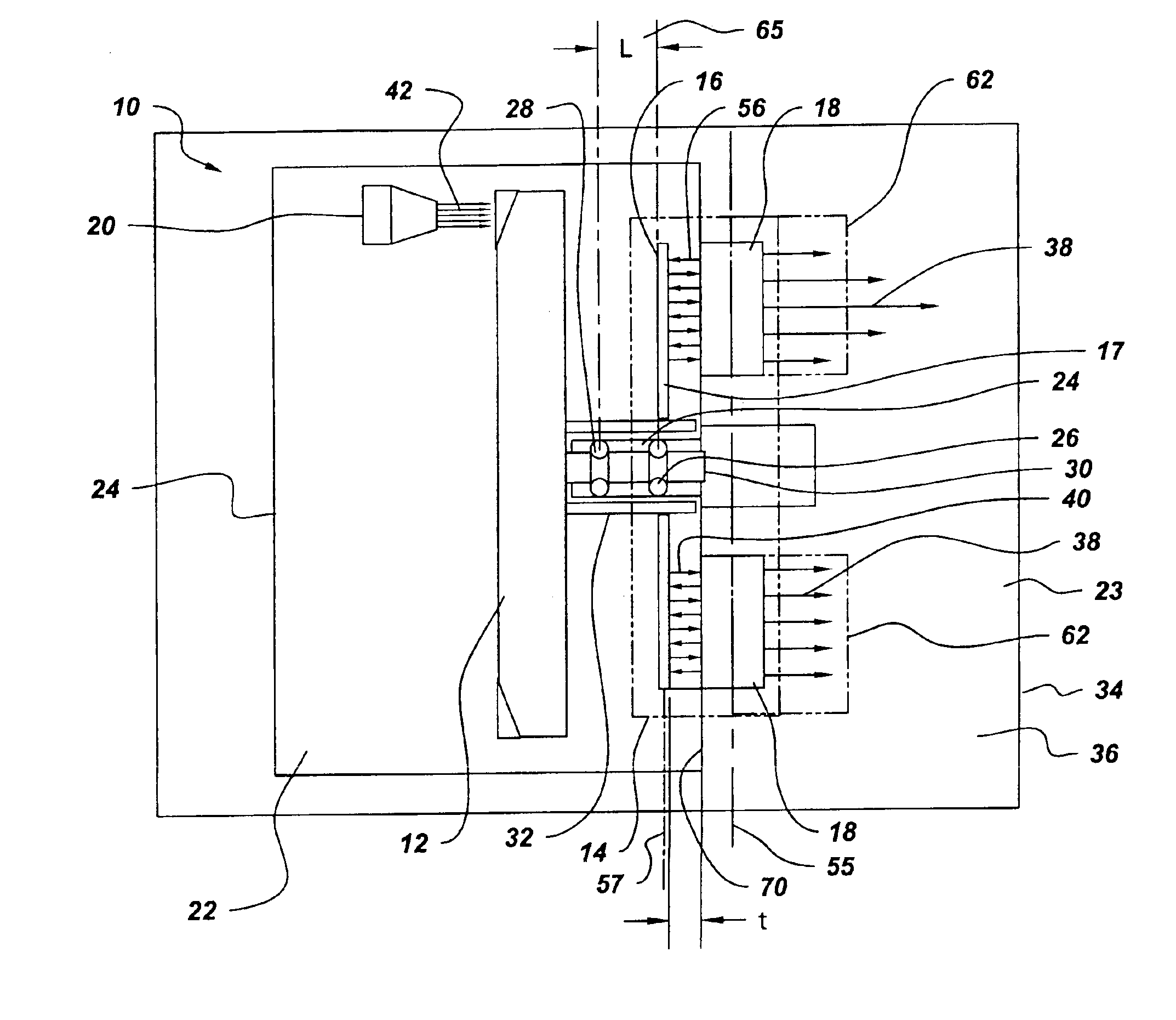
In accordance with another embodiment, an X-ray tube comprises an anode target assembly and an axial flux induction motor having a rotor and a stator. The stator is positioned along a transverse axis parallel to the rotor axis while the rotor is further configured to be integral with the anode target assembly. The axial flux induction motor further comprises a bearing assembly having at least two bearings and at least one bearing mount to support the anode target assembly. The anode target assembly is positioned between at least a first bearing and a second bearing of the at least two bearings. A cathode generates an electron beam for impingement upon the anode target assembly and a vacuum housing surrounds the anode target assembly and the cathode to enable the electron beam impingement.

Problems solved by technology

Such bearings experience excess mechanical load, such as static load and dynamic load, due to excess weight and centrifugal force of the rotating components, respectively.
Furthermore, the bearings are exposed to a substantial thermal load, generated due to impingement of the electron beam on the anode target assembly.
The mechanical load coupled with such thermal load experienced by the bearings poses a challenge to X-ray tube designers, particularly with regard to enhancing the bearing life so as to ensure trouble free operation of the X-ray generation system.
Although certain methods have been used to minimize the thermal load on X-ray tube bearings, issues pertaining to excess static load and dynamic load experienced by the bearings continue to pose a challenge to X-ray tube designers.
The typical mass distribution of the rotating components poses additional limitations on design of X-ray generation systems, particularly with regard to minimizing weight and improving overall compactness of the X-ray tube.

Method used


Image

  • Axial flux motor driven anode target for X-ray tube
  • Axial flux motor driven anode target for X-ray tube
  • Axial flux motor driven anode target for X-ray tube

Examples


Embodiment Construction

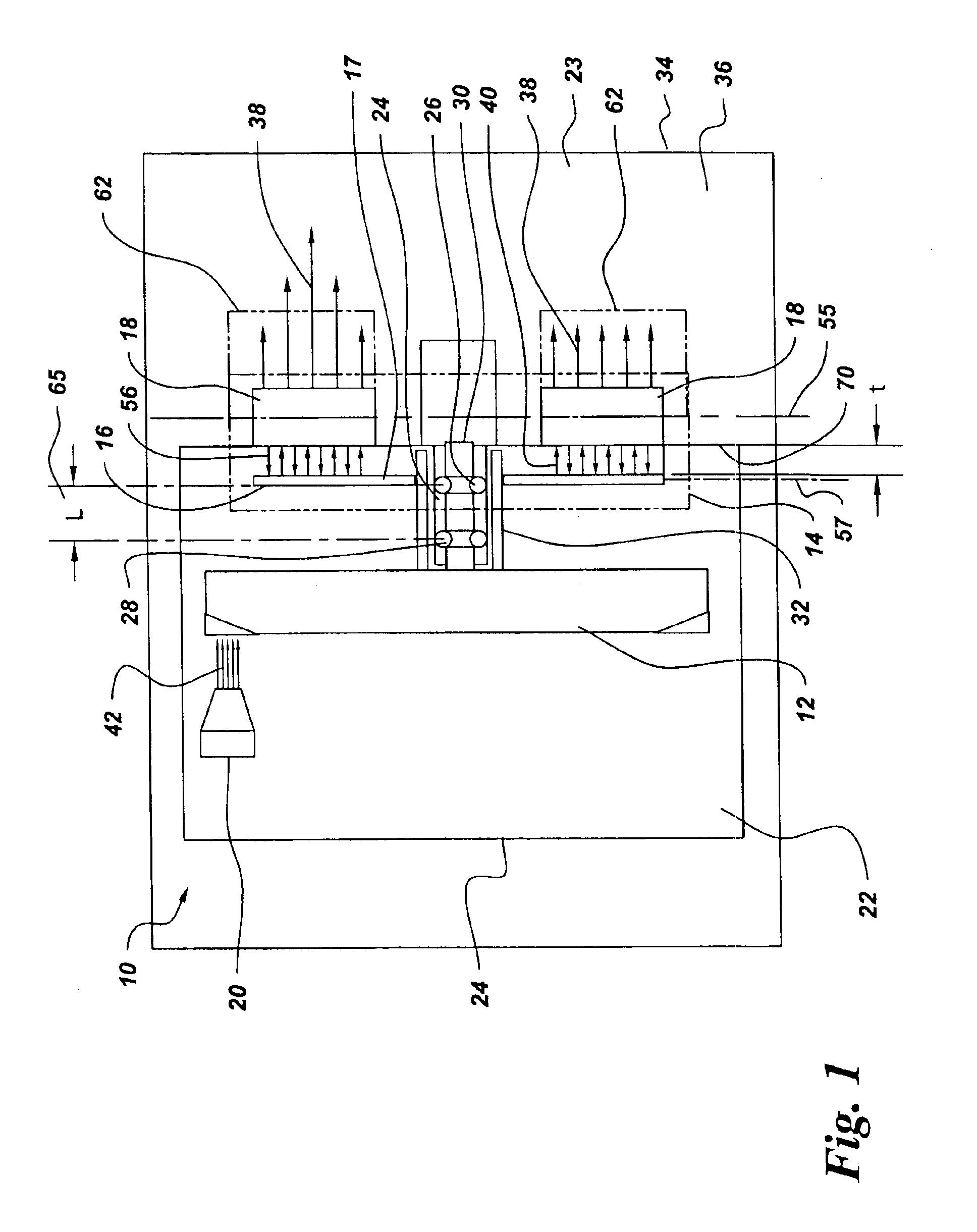
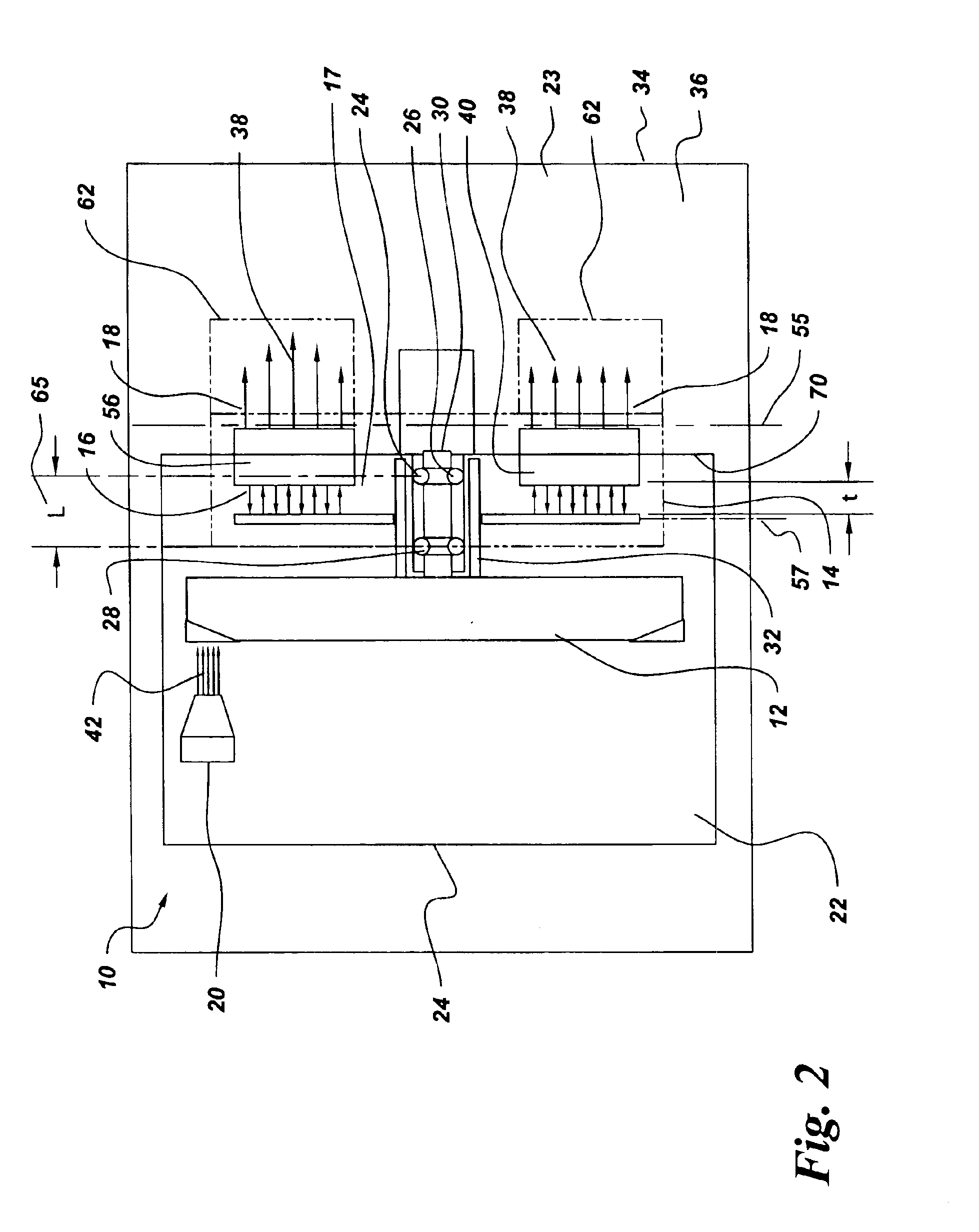
An X-ray generating device, also referred to as an X-ray tube 10, is depicted in FIG. 1 through FIG. 6. The X-ray tube 10 includes an anode target assembly 12. The anode target assembly 12 is generally fabricated from a metal having a relatively large atomic number such as tungsten or tungsten alloy, molybdenum or rhenium, for example. A cathode filament (not shown) disposed in a cathode assembly 20, is heated to emit an electron beam 42. A potential difference, typically on the order of about 60 kilovolts to about 140 kilovolts, is applied between the cathode assembly 20 and the anode target assembly 12 to accelerate the electron beam 42 generated by the cathode assembly 20. Once accelerated, the electron beam. 42 impinges on the anode target assembly 12 to generate electromagnetic radiation. Such electromagnetic radiation is typically X-ray radiation.

A portion of the kinetic energy of the electron beam 42, typically about 1%, is converted to the X-ray radiation, while the balance ...


PUM


Abstract

An X-ray tube comprises a cathode, an anode target assembly and an axial flux motor having a rotor and a stator. The stator is positioned along a transverse axis parallel to the rotor axis. The rotor and the stator are configured to be coupled to the anode target assembly. A cathode generates an electron beam for impingement upon the anode target assembly and a vacuum housing surrounds the anode target assembly, the cathode and the rotor to enable the electron beam impingement.

Description

BACKGROUND OF INVENTIONThe present invention relates generally to X-ray generation systems and more specifically to X-ray tubes driven by axial flux motors.An X-ray tube comprises an electron beam emitted from a cathode to strike an anode target assembly for producing X-rays. The electron beam is accelerated by a potential difference maintained between the cathode and the anode target assembly, typically on the order of about 60 kilovolts to about 140 kilovolts. The accelerated electron beam hits an anode target at a focal spot, generating the X-ray radiation thereby. Typically, only about one percent of the kinetic energy of the electron beam is converted to X-ray radiation. The remaining portion of the kinetic energy of the electron beam is converted to thermal energy. It is desirable to rotate the anode target assembly by a drive arrangement at a desired speed, to avoid local melting of the anode target assembly.In conventional X-ray generation systems, the X-ray tube anode targe...

Claims


Application Information

Patent Timeline
Patent Type & Authority Patents(United States)
IPC IPC(8): F16C33/04F16C33/10F16C33/66F16C32/04F16C19/02F16C19/18G21K5/00G21K5/08H01J35/16H01J35/26H01J35/28H01J35/24H01J35/10H01J35/00H05G1/66H05G1/00H02K21/12H02K21/24
CPCH01J35/10H01J35/26H01J2235/1208H01J2235/1026
Inventor TIWARI, MAYANKANBARASU, RAMASAMYOSAMA, MOHAMEDKLIMAN, GERALD BURT
Owner GENERAL ELECTRIC CO
Learn More