
Lift, propulsion and stabilising system for vertical take-off and landing aircraft

a technology for lifting, propulsion and stabilising systems, applied in the direction of vertical landing/take-off aircraft, rotocraft, aircraft navigation control, etc., can solve the problems of unstable, low lift, unstable, and complex, and achieve the effect of smooth and fair shap

Inactive Publication Date: 2012-11-08
SALZ MANUEL
View PDF4 Cites 75 Cited by
  • Summary
  • Abstract
  • Description
  • Claims
  • Application Information

AI Technical Summary

Benefits of technology

[0007]To provide large stability by using fans, tangential turbines and / or oscillating fins and / or air blasts, lifters and / or stabilisers, placing the horizontal lifters near at least one end of the longitudinal axis and of the transverse axis of the aircraft, stabilising fins at the exit of the rotors or the application of asymmetrical power by means of several rotors. Compensating quickly and efficiently, especially when electrical systems are used.
[0056]The aircraft will be built preferably with light or ultra light materials like carbon fiber or the like and the batteries, ultracapacitors, electric motors and generators have a high power-to-weight ratio.

Problems solved by technology

Aircrafts have little lift at low speed, they need maximum power, large wings and flaps for the takeoff and landing, they are dangerous because of their high speed next to the ground, they use heavy landing gears, large airports, expensive runways and do not carry out vertical takeoff.
Helicopters are slow, expensive, heavy, complex and have little autonomy.
Current VTOL and SVTOL aircrafts, with adjustable nozzles or not, have little safety or are unstable and do not efficiently exploit the energy of the turbines at low height and at low speed.
All are difficult to control.

Method used


Image

  • Lift, propulsion and stabilising system for vertical take-off and landing aircraft
  • Lift, propulsion and stabilising system for vertical take-off and landing aircraft
  • Lift, propulsion and stabilising system for vertical take-off and landing aircraft

Examples


Embodiment Construction

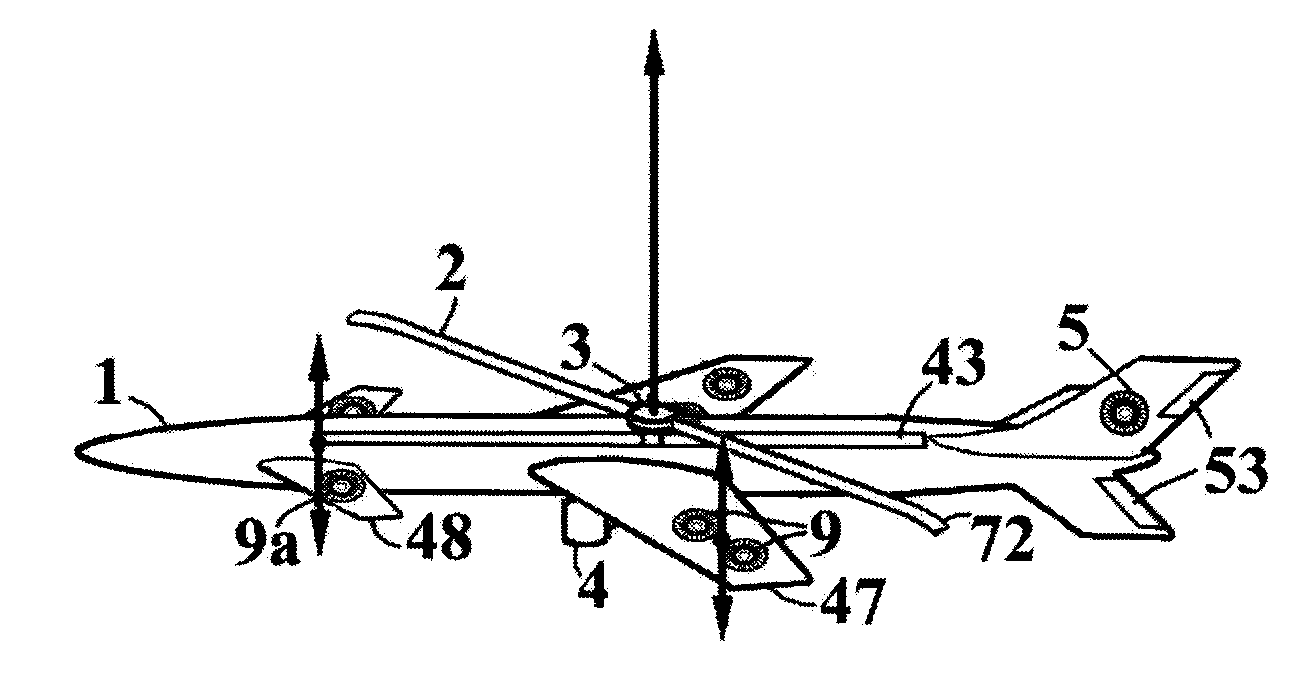
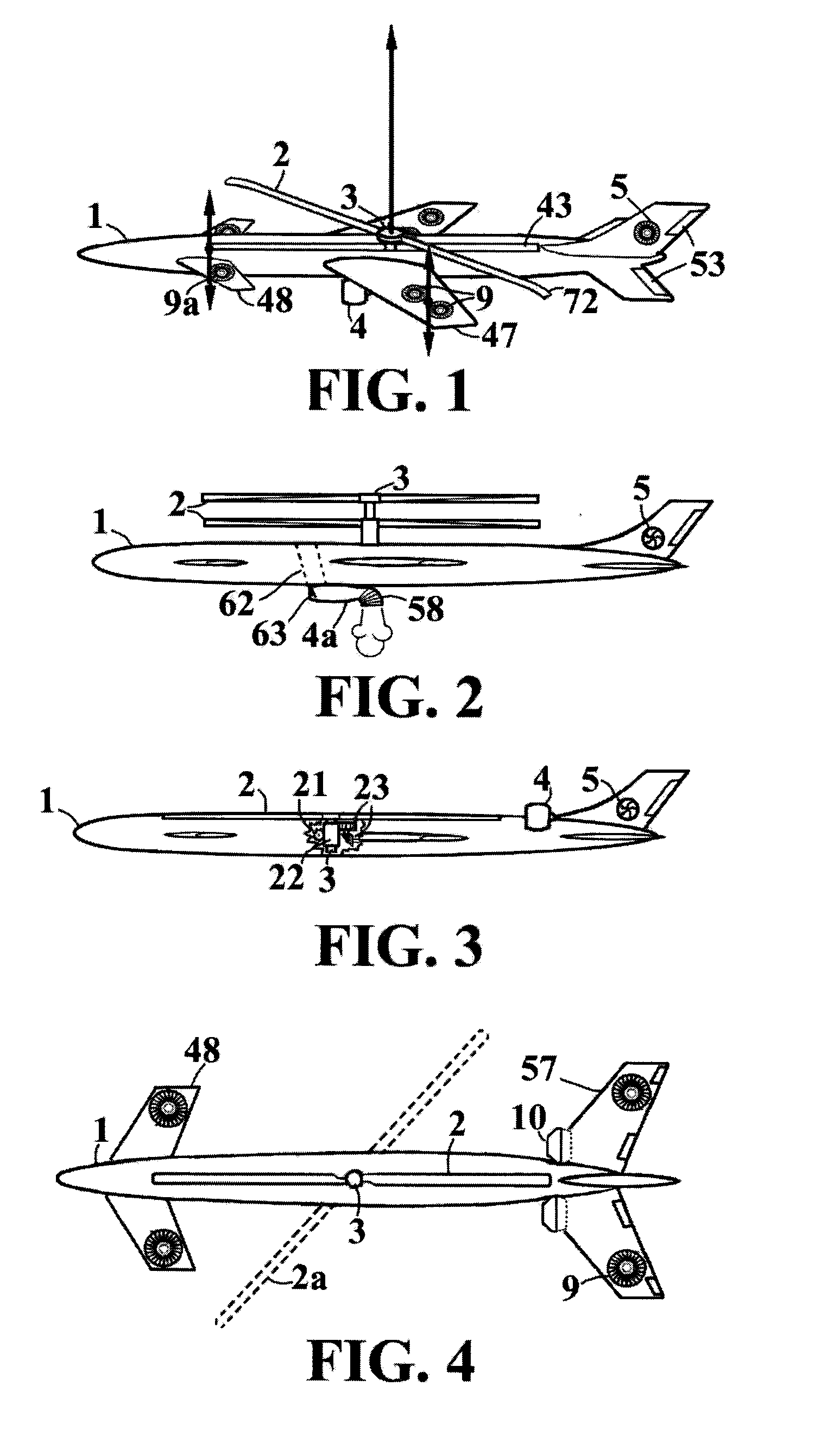
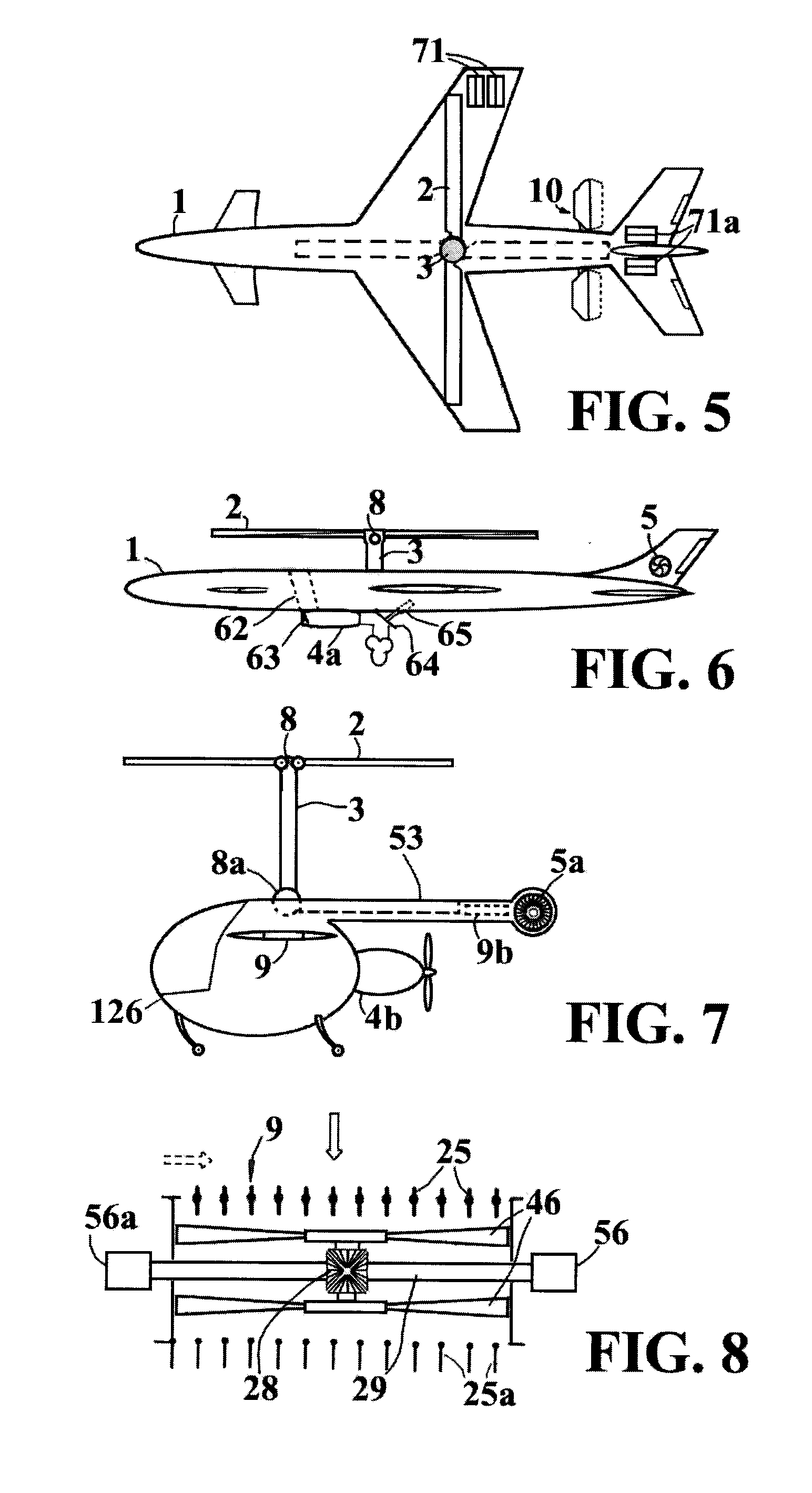
[0016]The lift, propulsion and stabilising system and method for vertical takeoff and landing aircraft of the invention consists of applying during vertical flight on, below or in the interior of the fixed-wing aircraft one or more rotors or large fans each one with two or more horizontal blades, said rotors are activated by means of turboshafts, turbofans or turboprops with a mechanical, hydraulic, pneumatic or electrical transmission, and the respective motors. Using lifting and / or stabilising and / or controlling fans and / or oscillating fins and / or air blasts. Placing the horizontal lifters near at least one end of the longitudinal axis and of the transverse axis of the aircraft. Generally said stabilising elements form 90° with one another and with the central application point of the rotor or application of that which results from the lift forces.

[0017]One or two rotors or large fans can be placed in the interior of ducts, or the rotors be streamlined with an aerodynamic profile ...


PUM


Abstract

The lift, propulsion and stabilising system for vertical takeoff and landing aircraft of the invention consists of applying during vertical flight on, below or in the interior of the fixed-wing aircraft one or more rotors or large fans each one with two or more horizontal blades, said rotors are activated by means of turboshafts, turbofans or turboprops with a mechanical, hydraulic, pneumatic or electrical transmission, and the respective motors. Using lifting and / or stabilising and / or controlling fans and / or oscillating fins and / or air blasts. Placing the horizontal lifters near at least one end of the longitudinal axis and of the transverse axis of the aircraft. Generally said stabilising elements form 90° with one another and with the central application point of the rotor or application of that which results from the lift forces.

Description

INDEX TO RELATED APPLICATIONS[0001]This application claims the benefit of PCT application PCT / ES2010 / 000204, filed May 5, 2010, which claims the benefit of Spanish patent application numbers, P201000248 filed Feb. 11, 2010, and P200901843 filed Aug. 26, 2009, the diclsosure of which are incorporated herein by reference in their entirety.FIELD OF THE INVENTION[0002]In systems for lift, propulsion and stabilisation of manned and unmanned aircraft, radio control, etc.STATE OF THE ART[0003]Aircrafts have little lift at low speed, they need maximum power, large wings and flaps for the takeoff and landing, they are dangerous because of their high speed next to the ground, they use heavy landing gears, large airports, expensive runways and do not carry out vertical takeoff. Helicopters are slow, expensive, heavy, complex and have little autonomy. Current VTOL and SVTOL aircrafts, with adjustable nozzles or not, have little safety or are unstable and do not efficiently exploit the energy of...

Claims


Application Information

Patent Timeline
IPC IPC(8): B64C29/00B64C27/30B64C27/26
CPCB64C27/26B64C29/0025B64C27/30
Inventor SAIZ, MANUEL MUNOZ
Owner SALZ MANUEL
Learn More