
Method for preventing electrostatic discharge in a clean room

a clean room and electrostatic discharge technology, applied in the direction of electrostatic charges, electrical equipment, energy-based chemical/physical/physical-chemical processes, etc., can solve the problems of electronic devices being damaged at about 10v, all integrated circuit manufacturers cannot afford to ignore, etc., to achieve the effect of preventing electrostatic discharge in a clean room

Inactive Publication Date: 2005-03-29
UNITED MICROELECTRONICS CORP
View PDF1 Cites 11 Cited by
  • Summary
  • Abstract
  • Description
  • Claims
  • Application Information

AI Technical Summary

Benefits of technology

The invention provides a method for preventing electrostatic charge in a clean room using a laminar flow apparatus with ion generators and transportation systems. The output tips of the ion generators face toward the ceiling of the clean room, which reduces the electric field strength to a desired value in a very short distance. The heights of the ionization systems and the relative sites for the transportation systems are adjusted to protect each transportation system and the cart from electrostatic charges and enlarge the area or range protected from electrostatic charges. The technical effects of the invention are to effectively prevent electrostatic charge in a clean room and to improve the cleaning efficiency.

Problems solved by technology

In recent years, electrostatic charge has become a serious problem, which all integrated circuit (IC) manufacturers cannot afford to ignore.
In the manufacturing and assembling processes of electronic devices, the electronic devices are sometimes apt to be damaged at about 10V.
If all electronic devices within a unit have completely broken down, the defect is easily detected by quality control.
However, if the electronic devices are slightly damaged, or if only a portion of the electronic devices have completely broken down, it is very difficult to identify performance deterioration of such devices by routine testing.
Broken or damaged devices are not always identified following processing, even upon the delivery to customers or when in use by customers.
A quality control procedure is difficult to implement and hence the loss and the impact incurred are unpredictable.
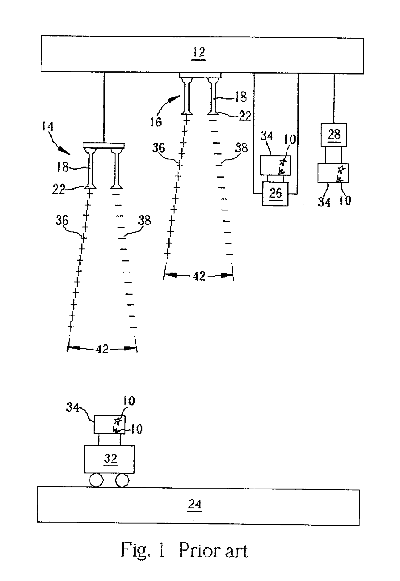
The electrostatic charges cannot be neutralized effectively and the materials carried in the carrier 34 of the automatic transportation system A 26 and the automatic transportation system B 28 may be damaged due to the excessive electric field strength.

Method used


Image

  • Method for preventing electrostatic discharge in a clean room
  • Method for preventing electrostatic discharge in a clean room
  • Method for preventing electrostatic discharge in a clean room

Examples


Embodiment Construction

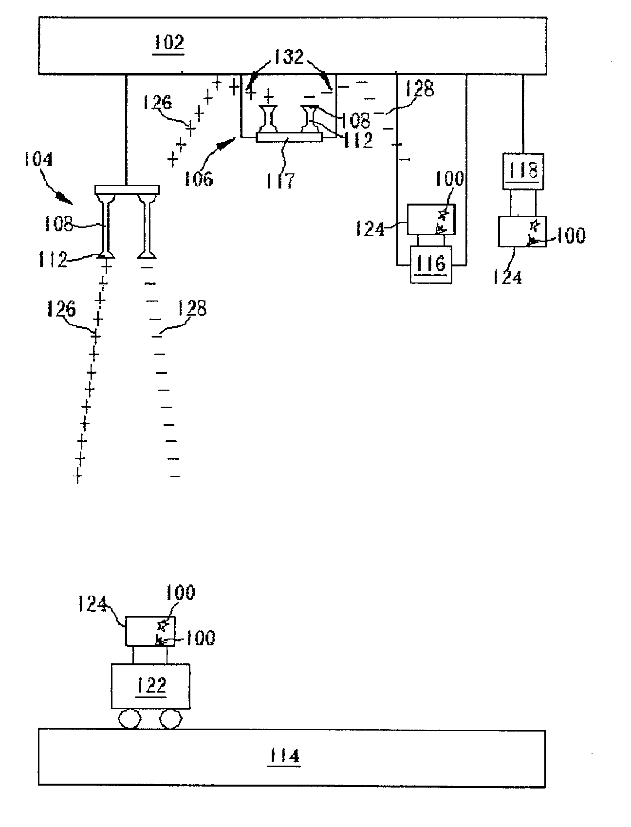
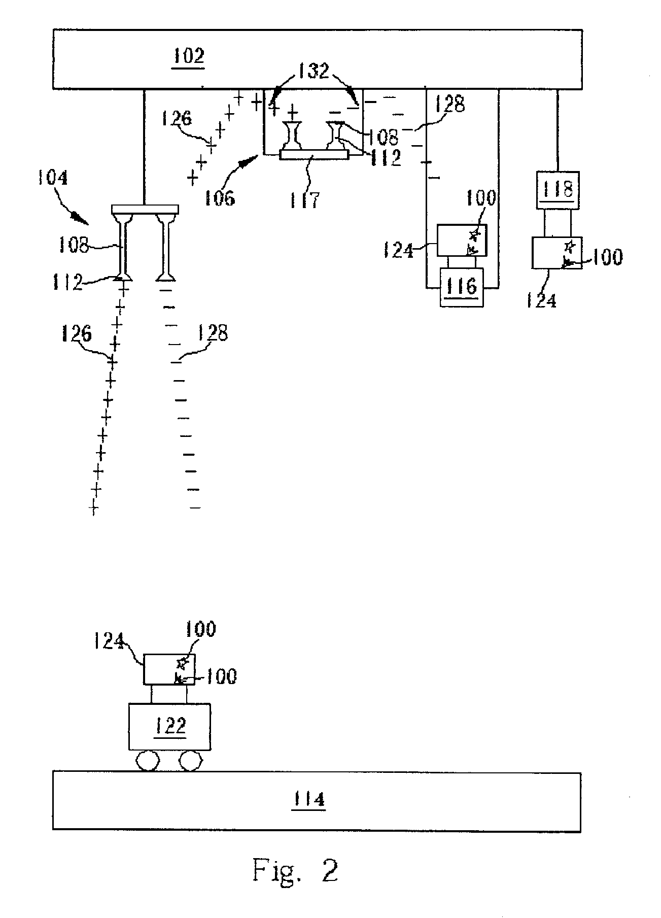
Please refer to FIG. 2 of a schematic diagram of a method for preventing electrostatic charges in a clean room according to the present invention. As shown in FIG. 2, the present invention method for preventing electrostatic charges 100 in a clean room is to dispose an ionization system A 104 and an ionization system B 106 in the clean room (clean room not shown). Both the ionization system A 104 and the ionization system B 106 are fixed on a ceiling 102 in the clean room. However, output tips 112 of emitters 108 of the ionization system A 104 face toward a floor 114 in the clean room and output tips 112 of emitters 108 of the ionization system B 106 face toward the ceiling 102 in the Clean room. The vertical distance between the Output tips 112 of the emitters 108 of the ionization system A 104 and the ceiling 102 is approximately 84 cm. The vertical distance between the top plate 117 of the ionization system B 106 and the ceiling 102 is approximately 30 cm. The actual vertical dis...


PUM


Abstract

The present invention provides a method of removing electrostatic charges from a clean room with a laminar flow apparatus. The laminar flow apparatus is disposed on a ceiling of the clean room. An ion generator at a first height and a transportation system at a second height are disposed in the laminar flow. An output tip of an emitter of the ion generator faces toward the ceiling to enlarge a divergent angle between positive and negative ions, effectively removing the electrostatic charges from the clean room and from a carrier in the transportation system.

Description

BACKGROUND OF THE INVENTION1. Field of the InventionThe present invention provides a method for removing electrostatic charges from a clean room with a laminar flow apparatus, and more particularly, to a method for preventing electrostatic discharge in a clean room.2. Description of the Prior ArtA modern clean room is not only able to remove the particles floating in the air quickly, but is also able to control the temperature, the humidity, the pressure, and to prevent electrostatic charges and electromagnetic interference. In recent years, electrostatic charge has become a serious problem, which all integrated circuit (IC) manufacturers cannot afford to ignore. The reason for this is because there is no regularity in the way the electrostatic charges are generated. In the manufacturing and assembling processes of electronic devices, the electronic devices are sometimes apt to be damaged at about 10V. If all electronic devices within a unit have completely broken down, the defect i...

Claims


Application Information

Patent Timeline
Patent Type & Authority Patents(United States)
IPC IPC(8): H05F3/04H05F3/00
CPCH05F3/04
Inventor CHANG, KUANG-YEH
Owner UNITED MICROELECTRONICS CORP
Learn More