
Method for making a moineau stator and resulting stator

a stator and moineau technology, applied in the direction of rotary or oscillating piston engines, engine lubrication, rotary piston engines, etc., can solve the problems of high complexity and slow machining methods, manufacturing exercises have proved to be very expensive, and solid metal stators have never been widely used on an industrial scal

Inactive Publication Date: 2005-03-29
PCM TECH
View PDF12 Cites 23 Cited by
  • Summary
  • Abstract
  • Description
  • Claims
  • Application Information

AI Technical Summary

Benefits of technology

It is therefore an object of the invention to simultaneously remedy the various disadvantages listed hereinabove and to propose improvements to the manufacture and structure of Moineau pump stators which are able to satisfy the various requirements of practical life, particularly as regards the rigidity of the stator cavity, the structural simplicity of the stator and the performing of the manufacturing process.
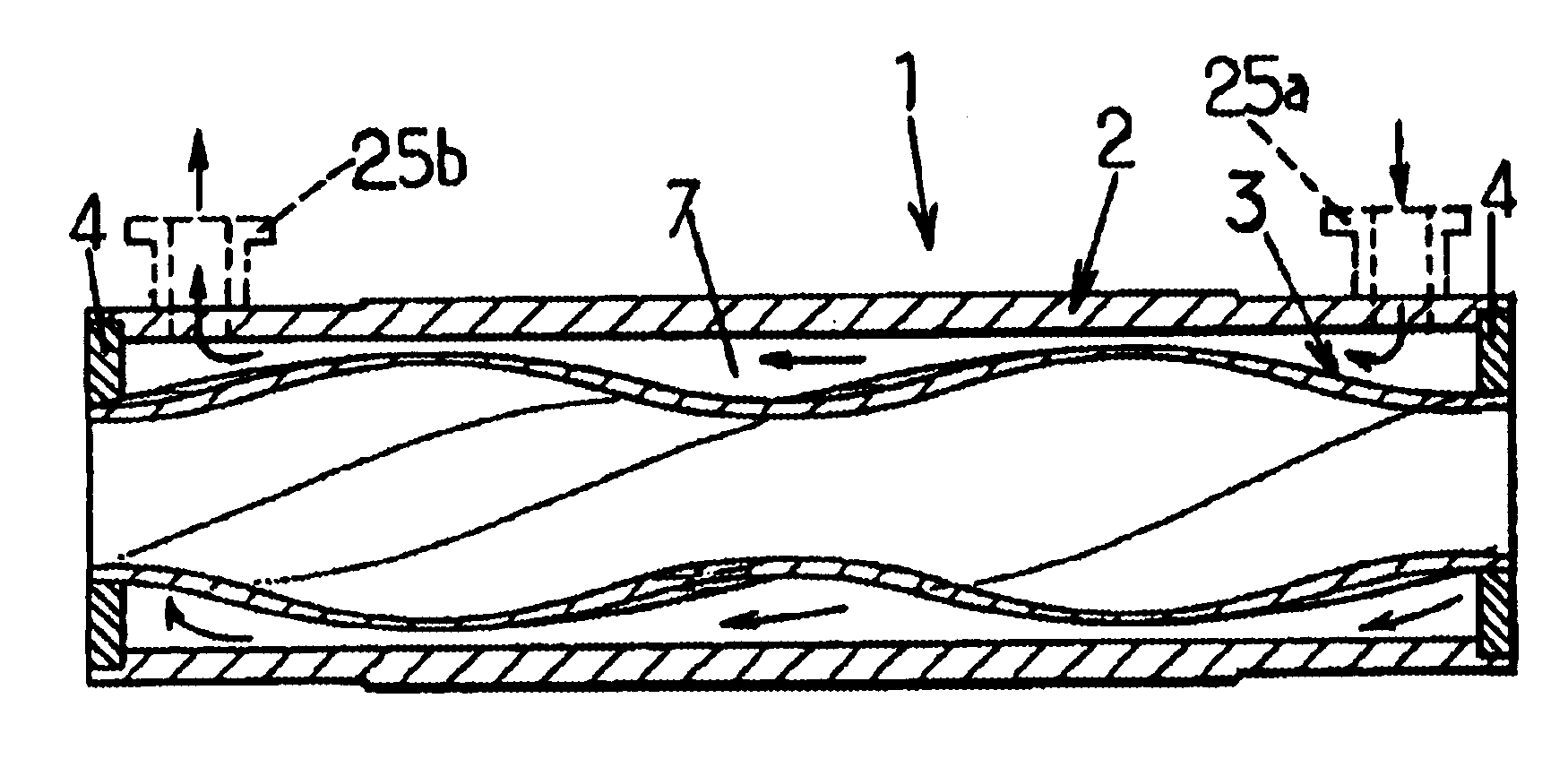
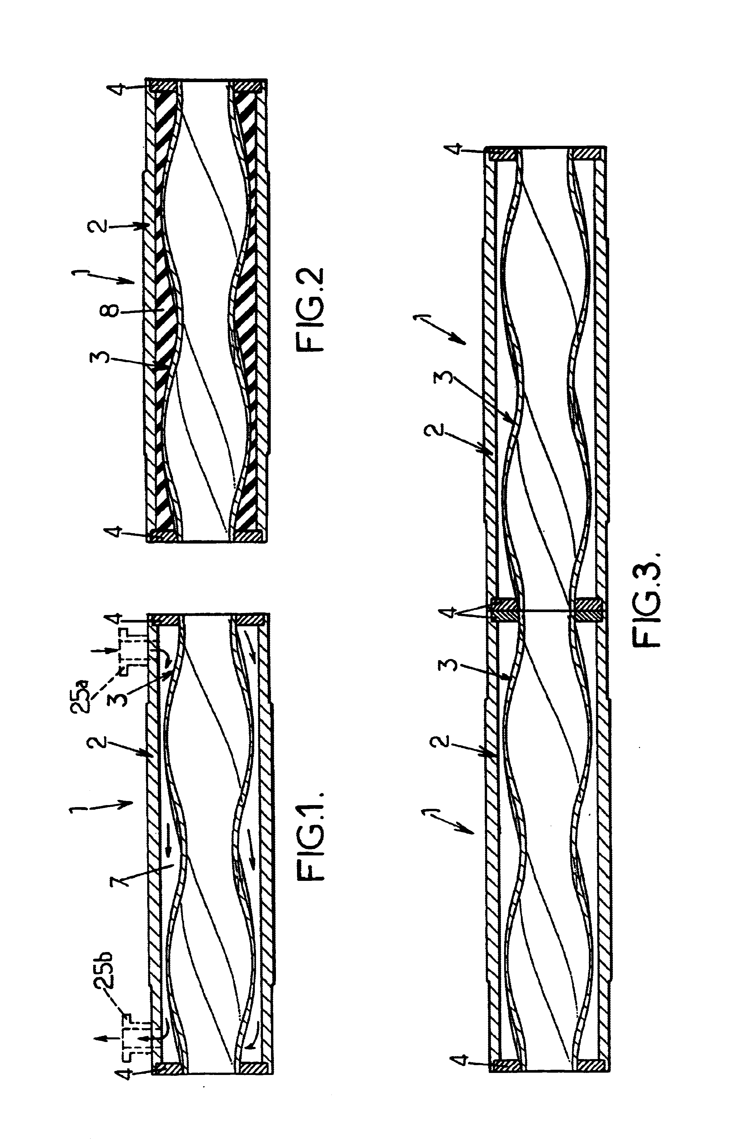
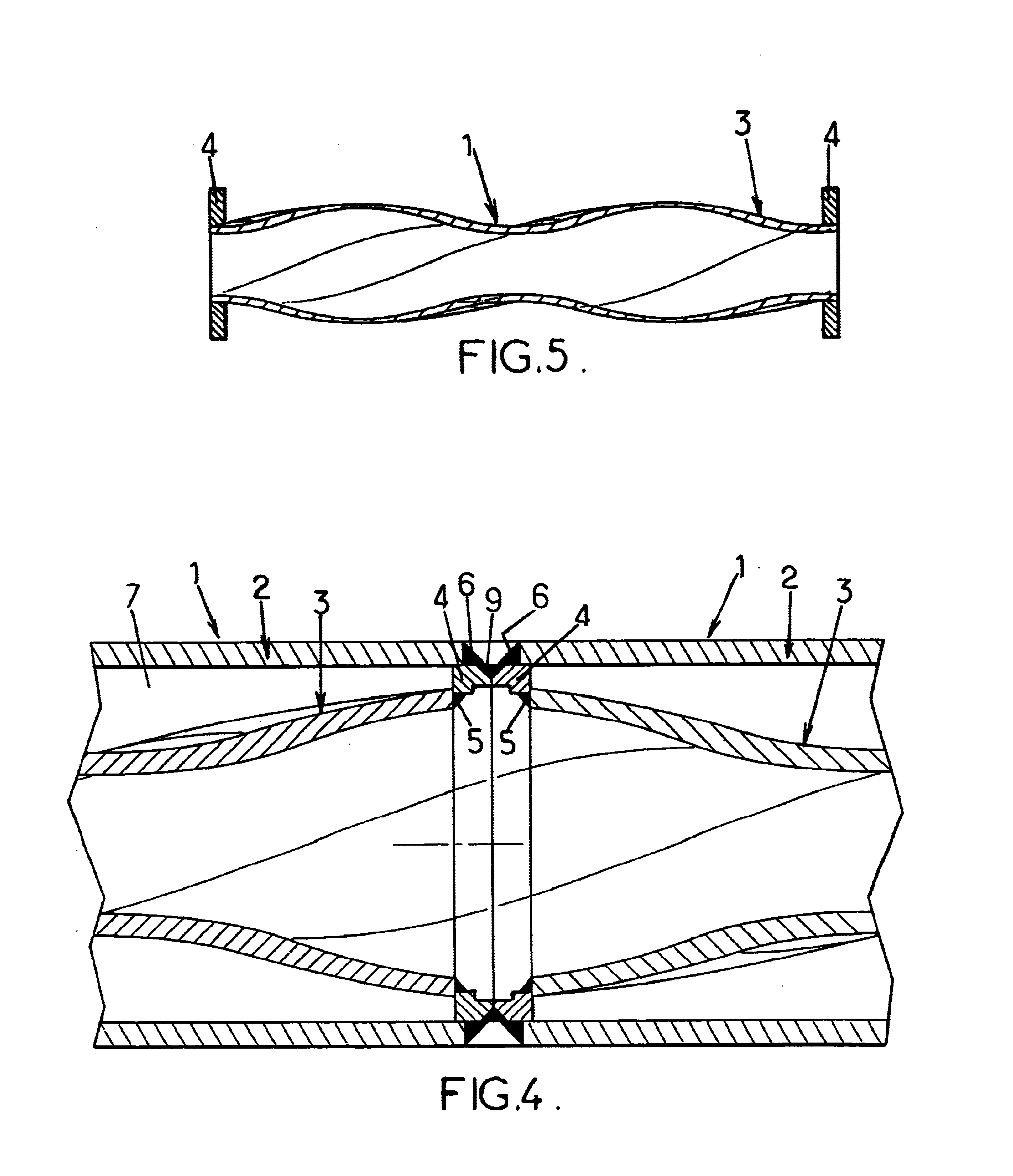
By virtue of the implementation of the method according to the invention, it is possible to produce a tubular metal element forming a stator cavity which has a wall of relatively great thickness and which, as a result, is perfectly rigid and self supporting: this tubular element can be joined to the housing only by its ends, hence greatly simplifying the assembly and allowing a lower cost, and one can be sure of maintaining the clearance between the rotor and the stator along the entire length of the pump.
In spite of the relative thickness of the initial tube (for example of the order of 3.5 mm for a diameter of the order of 65 mm), it is possible to obtain a tubular element that meets all the necessary requirements, in spite of the individual insufficiencies of the process used: the preliminary mechanical forming makes it possible to introduce significant local radial deformations in spite of the appreciable thickness of the wall that is to be formed, but without it being possible to achieve good precision on shape; by contrast, the process of hydroforming under very high pressure (for example of the order of 4000×105 Pa) makes it possible to achieve precise forming on the core, but on the condition that the amplitude of the localized radial deformation is relatively small.
The combination of the two processes of mechanical deformation and of hydroforming, conducted in two successive steps, makes it possible to reap their individual advantages and set aside their disadvantages, and therefore to succeed in manufacturing, under economical conditions, a stator with a cavity made of metal that can be used in forming Moineau pumps able to operate under arduous conditions.
As to the fundamental final step involving the hydroforming process, this may be performed by compressing the rough form onto a core placed inside it, which leads to the transfer, by direct contact with the outer surface of the core and the inner surface of the rough form, of the exact shape and the precise dimensions from the core to the stator cavity; alternatively, it may be performed by expanding the rough form inside a mold, something which entails good control over the deformation of the metal and good control over its thickness so that the shaping of the outer face of the tubular element in contact with the mold results, on its inner face, in exact shaping and precise sizing of the stator cavity.
According to the anticipated applications of the pump, the annular gap defined between the tubular metal element forming the stator cavity and the housing may be filled with a rigid filler material, for example a thermosetting resin or a cement, able to enhance the resistance to vibration of the means that join the tubular element and the housing together.

Problems solved by technology

However, these have been solid metal stators, of which the cavity of complex shape has been excavated from a block of metal using highly complex and slow machining methods.
These manufacturing exercises have proved to be very expensive, which means that solid metal stators have never been widely used on an industrial scale and have remained at an almost prototype stage (in the food industry in particular).
A stator formed in this way restricts the field of use of the pump, firstly because of the clamping of the rotor by the stator (which excludes pumps for abrasive or highly viscous products—such as heavy crude oils-) and secondly, because of the presence of the filling material such as an elastomer (which excludes pumps intended to operate in high-temperature environments—such as pumps for extracting crude oil from deep wells-).
What is more, the presence of three main constituent parts (tubular element forming the stator cavity, housing, filling material) leads to a relatively high cost.
Such a method presents or introduces several disadvantages which, here again, limit the field of use of pumps equipped with the stators obtained.
A first disadvantage lies in the fact that the process of deforming, particularly via a hydraulic route, the initial tubular portion is conducted inside the housing of the stator, which then acts as a pressure chamber.
It is then necessary to overengineer the housing so that it can mechanically withstand the forming pressures, even though thereafter this overengineering becomes needless when the pump is in operation.
This entails that the known process be limited to the deformation of tubular portions with fairly small wall thicknesses, leading to tubular elements forming stator cavities that have relative deformability.
However, in other types of pump where a clearance that needs to be kept as constant as possible is required between the stator and the rotor, such deformability would constitute a prohibitive handicap.
As a result, the forming of the tubular metal element forming the stator cavity directly, and in a single pass from the tubular portion that is initially cylindrical of revolution, here again limits this process to the processing of parts with fairly small wall thicknesses.

Method used


Image

  • Method for making a moineau stator and resulting stator
  • Method for making a moineau stator and resulting stator
  • Method for making a moineau stator and resulting stator

Examples


first embodiment

illustrated in FIG. 8, the rough form 12 is slipped over a core 15 which, externally, has the exact desired shaping for the stator cavity. The rough form / core assembly is placed in a closed chamber 16 (hydroforming chamber) that is filled with a liquid 17. By pressurizing this liquid, the rough form 12 is crushed (arrows 18) onto the core 15: this then constitutes the tubular metal element 3 the inner face of which is shaped exactly to the external shape of the core 15 (hydroforming by compression onto an internal core).

second embodiment

illustrated in FIG. 9, the rough form 12 is introduced into a mold 19 having a cavity 20 shaped to the exact shape to be given to the tubular element 3 that is to form the stator cavity. The ends of the rough form 12 are hermetically sealed and the interior volume of the rough form is filled with liquid 17. By pressurizing this liquid, the rough form 12 is crushed (arrows 18) against the wall of the molding cavity 20: this then constitutes the tubular element 3 (hydroforming by expansion against an external mold).

It will be noted that, in the process of hydroforming by compression onto an internal core, it is the interior face of the tubular element 3 (that is to say strictly speaking the face defining the stator cavity itself) which is brought into contact with the core and which directly and closely adopts the shape of the latter. By contrast, in the process of hydroforming by expansion against the wall of the molding cavity, it is the outer face of the tubular element 3 which is ...


PUM

PropertyMeasurementUnit
Electrical resistanceaaaaaaaaaa

Abstract

The invention concerns a Moineau type gear pump stator (1), comprising a stator cavity with global axial extension inside an elongated body, characterised in that the stator cavity is defined by a rigid-walled metal tubular element (3) having internall the shape and dimensions of the stator cavity such that, when it is assembled with a rotor, a positive clearance with the rotor is obtained.

Description

CROSS-REFERENCE TO RELATED APPLICATIONSThis application is the U.S. national phase of International Application No. PCT / FR02 / 02052 filed on Jun. 14, 2002, which application claims priority to French Application No. 01 08189 filed on Jun. 21, 2001, the contents of which are incorporated herein by reference.FIELD OF THE INVENTIONThe present invention falls within the field of Moineau-type gear pumps, also known as progressive cavity pumps, and it relates more especially to improvements made to the manufacture and structure of the stators of such pumps, these stators comprising a stator cavity of helical shape running axially overall inside an elongate body.DESCRIPTION OF THE PRIOR ARTGiven the highly complex shape of the stator cavity of this type of pump, the stator is usually made of a molded elastomer enclosed inside a rigid housing. Such an arrangement is satisfactory in many applications for which the temperature of the product to be displaced is below a 140° C., the maximum temp...

Claims


Application Information

Patent Timeline
IPC IPC(8): F04C2/107F04C2/00
CPCF04C2/1075Y10T29/49236F04C2230/27
Inventor LEMAY, LIONELCHOPARD, JEAN-PIERRE
Owner PCM TECH
Learn More