Output stage, amplifier and associated method for limiting an amplifier output

a technology of output stage and amplifier, applied in the field of electrical circuits, can solve problems such as input error and voltage level of clamping, and achieve the effects of facilitating the implementation of various amplifier configurations, facilitating clamping, and reducing overhead

Inactive Publication Date: 2005-03-22
TEXAS INSTR INC
View PDF9 Cites 6 Cited by
  • Summary
  • Abstract
  • Description
  • Claims
  • Application Information

AI Technical Summary

Benefits of technology

By implementing the clamping buffer in the output stage in such a manner, clamping can be facilitated. Such an arrangement also facilitates implementing various amplifier configurations (e.g., inverting, non-inverting, etc.) with little or no overhead. Additional efficiencies in operation and design can be achieved, for example, by implementing the output stage as part of an amplifier system in an integrated circuit and / or by configuring the clamping buffer and the input buffer to share one or more components to facilitate biasing the output.
According to another aspect of the present invention, the input buffer and the clamping buffer can be coupled to drive an associated output circuit through an arrangement of one or more biasing networks. This further enables the clamping buffer to be implemented with substantially smaller components than the output circuit. As a result, the overall footprint size for the output stage can be reduced by implementing an amplifier integrated circuit according to such an arrangement.

Problems solved by technology

Additionally, since the clamping is implemented at the input of the amplifier, the clamp voltage levels and input error are multiplied by the amplifier's closed loop gain at the output.

Method used


Image

  • Output stage, amplifier and associated method for limiting an amplifier output
  • Output stage, amplifier and associated method for limiting an amplifier output
  • Output stage, amplifier and associated method for limiting an amplifier output

Examples


Embodiment Construction

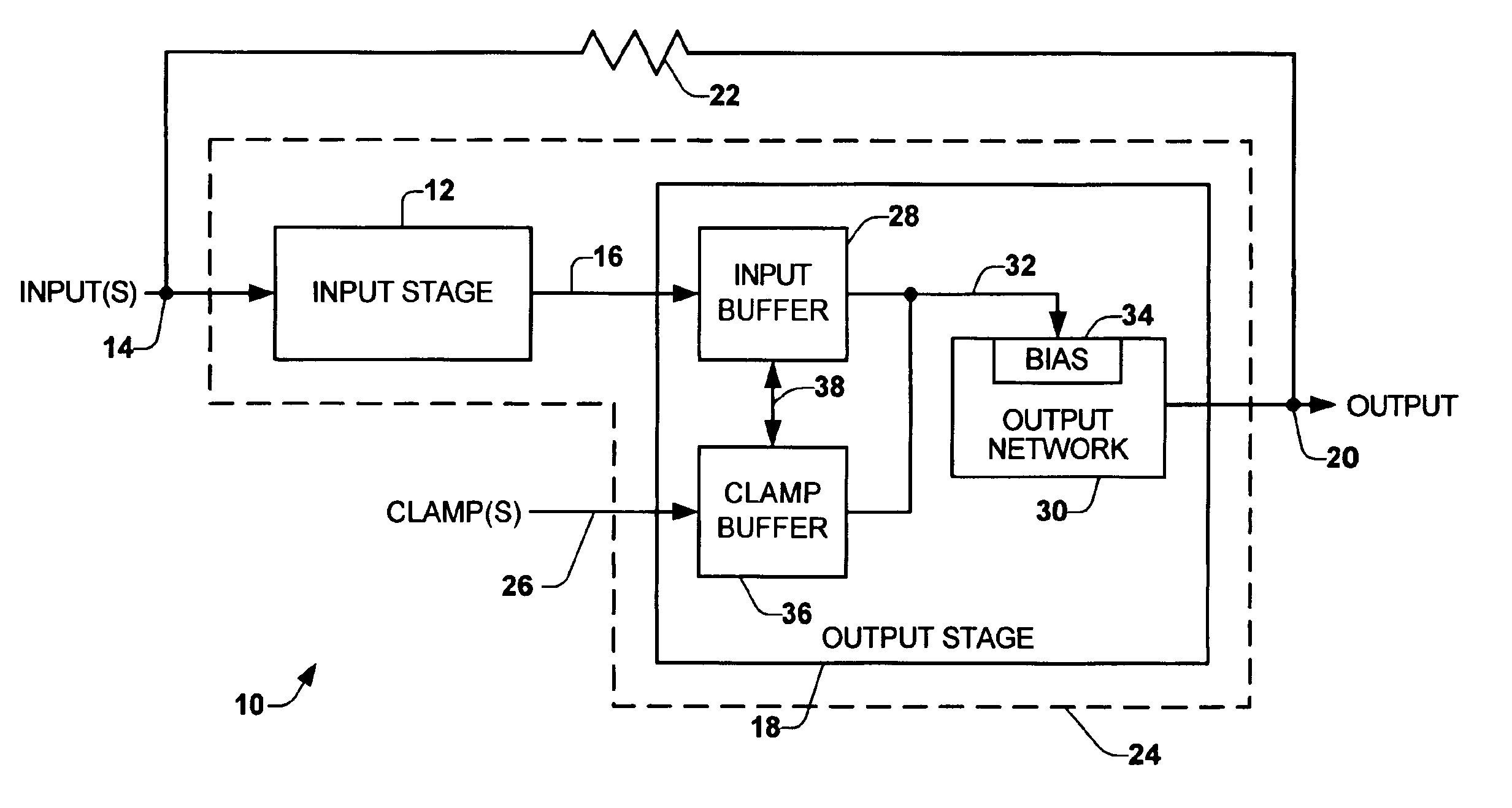
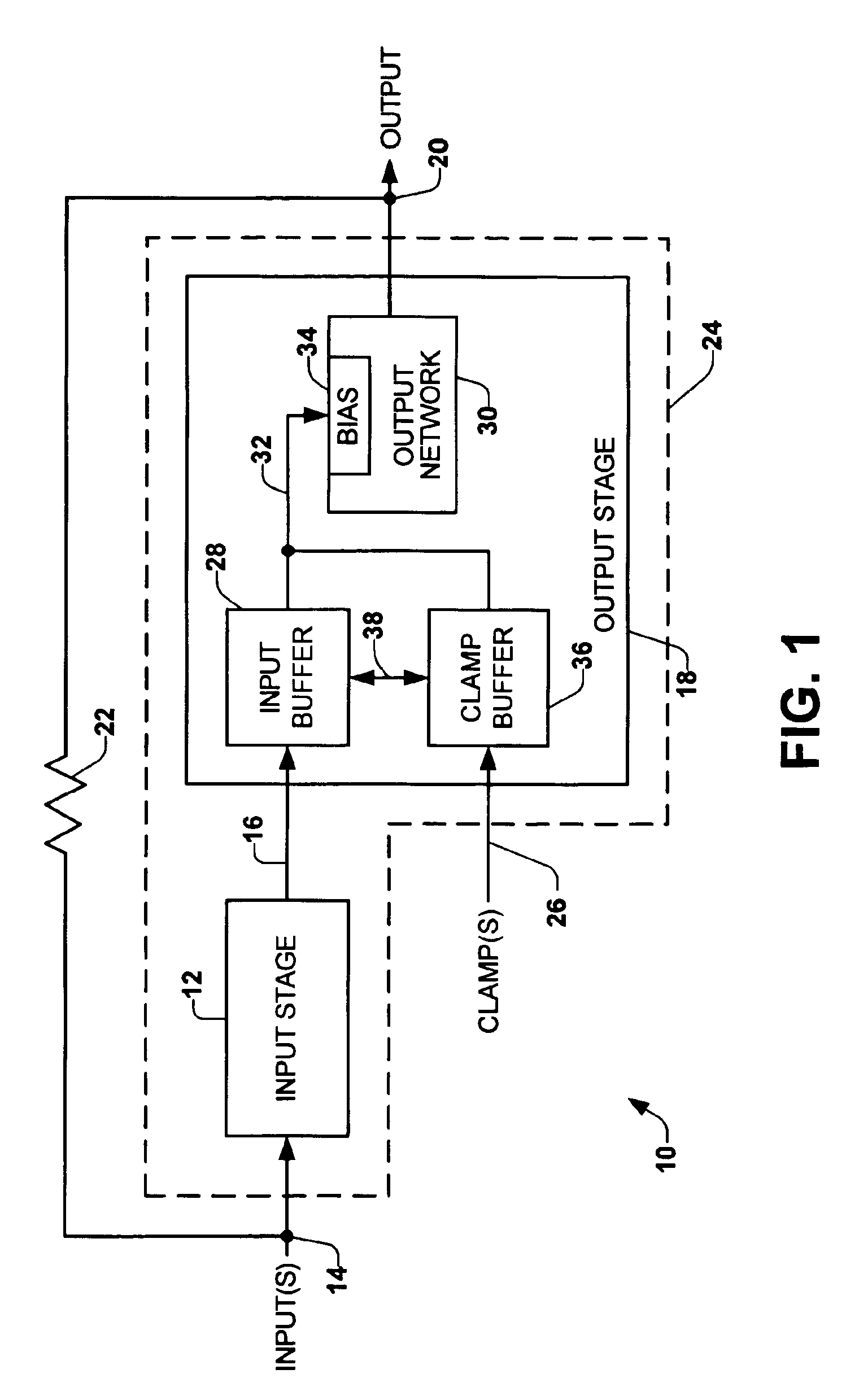
The present invention relates generally to a system and method for implementing an amplifier capable of limiting or clamping an amplifier output signal. A clamp buffer and an input buffer cooperate to bias an output circuit according to the relative level of a clamp signal and an input signal. In a normal mode, in which the input signal has a first relationship with the clamp signal, the output circuit provides an output signal based on the input signal. In a clamping mode, in which the input signal has a second relationship with the clamp signal, the output circuit provides an output signal based on the clamp signal, which can be substantially fixed. The clamp signal can be set by the user to establish a desired clamping range.

FIG. 1 depicts an example of an amplifier 10 that can be implemented in accordance with an aspect of the present invention. The amplifier 10 includes an input amplifier stage 12 that receives one or more input signals 14 and provides an intermediate signal at...


PUM


Abstract

A system and method for implementing an amplifier capable of limiting or clamping an amplifier output signal is described. A clamp buffer and an input buffer cooperate to bias an output circuit according to the relative level of a clamp signal and an input signal. In a normal mode, in which the input signal has a first relationship with the clamp signal, the output circuit provides an output signal based on the input signal. In a clamping mode, in which the input signal has a second relationship with the clamp signal, the output circuit provides an output signal based on the clamp signal, which can be substantially fixed. The clamp signal can be set by the user to establish a desired clamping range.

Description

TECHNICAL FIELDThe present invention relates to electrical circuits and, more particularly, to an output stage, amplifier and associated method for limiting an output signal.BACKGROUND OF INVENTIONVarious types of amplifier circuits have been developed for a myriad of applications, such as including audio applications, video applications and communications applications to name a few. Some core considerations for most amplifier designs are the ability to support a wide bandwidth and provide low distortion in the amplified output signal.In certain circumstances, it is desirable to limit the upper and / or lower bounds of an amplifier output voltage. Consequently, a type of amplifier generally referred to as voltage limiting or clamping amplifier has been developed. Clamping amplifiers are useful to enable a user to protect downstream circuitry, such as from over driving input signals to the amplifier. Thus, clamping amplifiers can be utilized in various amplifier configurations for audi...

Claims


Application Information

Patent Timeline
Patent Type & Authority Patents(United States)
IPC IPC(8): H03F3/26H03F3/45H03F1/30H03F3/30
CPCH03F3/3076H03F1/303
Inventor DASHTESTANI, AHMADHALBERT, JOEL MARTINVARNER, ALAN LEE
Owner TEXAS INSTR INC
Why Eureka
Try Eureka