
Distributed-object development system and computer-readable recording medium recorded with program for making computer execute distributed-object development

Inactive Publication Date: 2005-03-15
FUJITSU LTD
View PDF17 Cites 92 Cited by
  • Summary
  • Abstract
  • Description
  • Claims
  • Application Information

AI Technical Summary

Benefits of technology

It is an object of the present invention to provide a distributed-object development system and a computer-readable recording medium recorded with a program for making a computer execute the distributed-object development system, where the distributed-object development system is equipped with a simulator in each of a client application that forms a pair with a server application of which execution is to be verified and a server application that forms a pair with a client application of which execution is to be verified, thereby to avoid the need for a development of a test application, and the distributed-object development system is capable of dividing the environment of developing the client application from the environment of developing the server application, and is also capable of building up an environment for developing applications on a desired host system.
Further, the recording medium is recorded with a response generation procedure for generating a response according to a call request for the object from the client application based on interface information obtained in the interface information obtaining procedure, when the simulation of the server application has been selected in the selection procedure, a server simulation procedure for transmitting to the client application the response generated in the response generation procedure, a request generation procedure for generating a call request for the object based on interface information obtained in the interface information obtaining procedure, when the simulation of the client application has been selected in the selection procedure, and a client simulation procedure for transmitting to the server application a request generated in the request generation procedure and receiving a response transmitted from the server application according to the request. Therefore, it is possible to automatically build up a function for simulating the server application.

Problems solved by technology

However, as the scale of the network becomes larger and the applications for providing the above services become higher functional, there have been problems of increase in the communication traffics and increase in the load of servers.
Further, the development of applications becomes more complex.
However, when the network has become widely distributed, the conventional method of separately carrying out the application development and the build up of installation environment including communication and resource management and fault measures becomes a heavy load on the application development staffs.
This method also provides a lot of difficulties to these development staffs.
However, when the server application that has been in actual operation on the network is used for verifying the execution of the program, there is a risk that this server application is destroyed depending on the client application tested or that this gives inconvenience to other objects on the network.
Therefore, the use of the server application for the verification in this way is not practical.
In general, the application development staff of the CORBA-based system cannot find the server that is relevant to his or her own object.
Therefore, this requirement has been a very heavy load on the application development staff.
Therefore, it is not possible to completely reenact the application operation particularly on the ORB under the actual environment of the distributed objects via the network.
On the other hand, there is a risk that the existence of a bug gives a bad influence to other nodes (other clients or servers) connected to the network.
However, when it is not possible to know an accurate position of the target object based on the CORBA specification, particularly when a dynamic startup is to be carried out, it is not practicable to mount a debugger machine on each of the servers that have target objects.

Method used


Image

  • Distributed-object development system and computer-readable recording medium recorded with program for making computer execute distributed-object development
  • Distributed-object development system and computer-readable recording medium recorded with program for making computer execute distributed-object development
  • Distributed-object development system and computer-readable recording medium recorded with program for making computer execute distributed-object development

Examples


Embodiment Construction

Embodiments of a distributed-object development system and a computer-readable recording medium recorded with a program for making a computer execute the development of distributed objects will be explained in detail below with reference to the drawings. It should be noted that the invention is not limited to these embodiments.

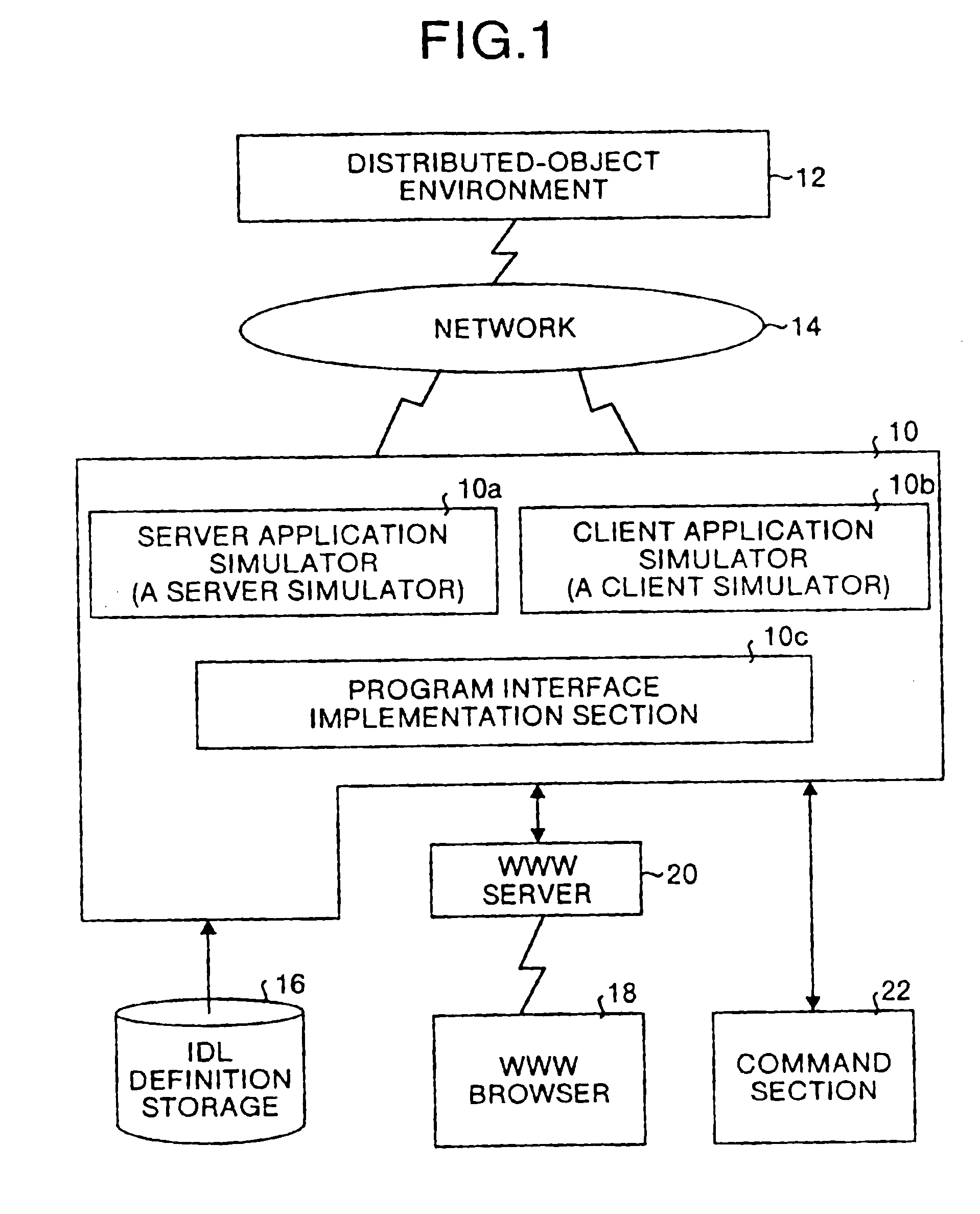
FIG. 1 is a block diagram that shows a schematic structure of a distributed-object development system relating to the present invention. In FIG. 1, a plurality of nodes such as PCs, WSs, host computer, etc., each being equipped with an object as a part of distributed objects, are connected to a network 14 built up based on communication protocols such as IIOP that are network protocols for communications between ORBs according to MG specifications. Thus, a distributed-object environment 12 has been established based on the CORBA or the like. Under this environment, the distributed-object development system is constructed by a simulator machine 10 that is conne...


PUM


Abstract

A simulator machine obtains IDL information from an IDL definition storage, and automatically builds up a function of a server application or a client application based on the IDL information obtained. The simulator machine is connected to a WWW server that is one of nodes. Each of the rest of the nodes can access the WWW server by starting a WWW Browser thereby to build up on its own node a function of a server simulator or a client simulator that is provided by the simulator machine.

Description

FIELD OF THE INVENTIONThe present invention relates to a distributed-object development system for supporting the development of client / server applications by object-oriented programming in a distributed object system in which objects that are distributed in a network function as a total by mutual co-operation and a computer-readable recording medium recorded with a program for making a computer execute the development of distributed objects.BACKGROUND OF THE INVENTIONIn recent years, along with improvement in the arrangement of communication infrastructures and wide distribution of LANs (local area networks) and internet services, there have been progressed remarkable developments in distributed computing systems from which terminal computers can enjoy desired services via a network. According to a conventional integrated data-processing type host-computer system, a high-performance host computer has carried out a necessary processing for the utilization of a database or for a comp...

Claims


Application Information

Patent Timeline
IPC IPC(8): G06F11/28G06F15/16G06F19/00G06F9/06G06F9/44G06F9/46G06F11/36
CPCG06F9/465
Inventor KUBOTA, YASUOSHIBA, NOBUO
Owner FUJITSU LTD
Learn More