
Data adaptive interference suppression

a data adaptive and interference suppression technology, applied in the direction of direction/deviation determining electromagnetic systems, instruments, using reradiation, etc., can solve problems such as errors in phase shift estimations and notches that are not steered in the proper direction

Inactive Publication Date: 2005-03-15
LOCKHEED MARTIN CORP
View PDF7 Cites 15 Cited by
  • Summary
  • Abstract
  • Description
  • Claims
  • Application Information

AI Technical Summary

Benefits of technology

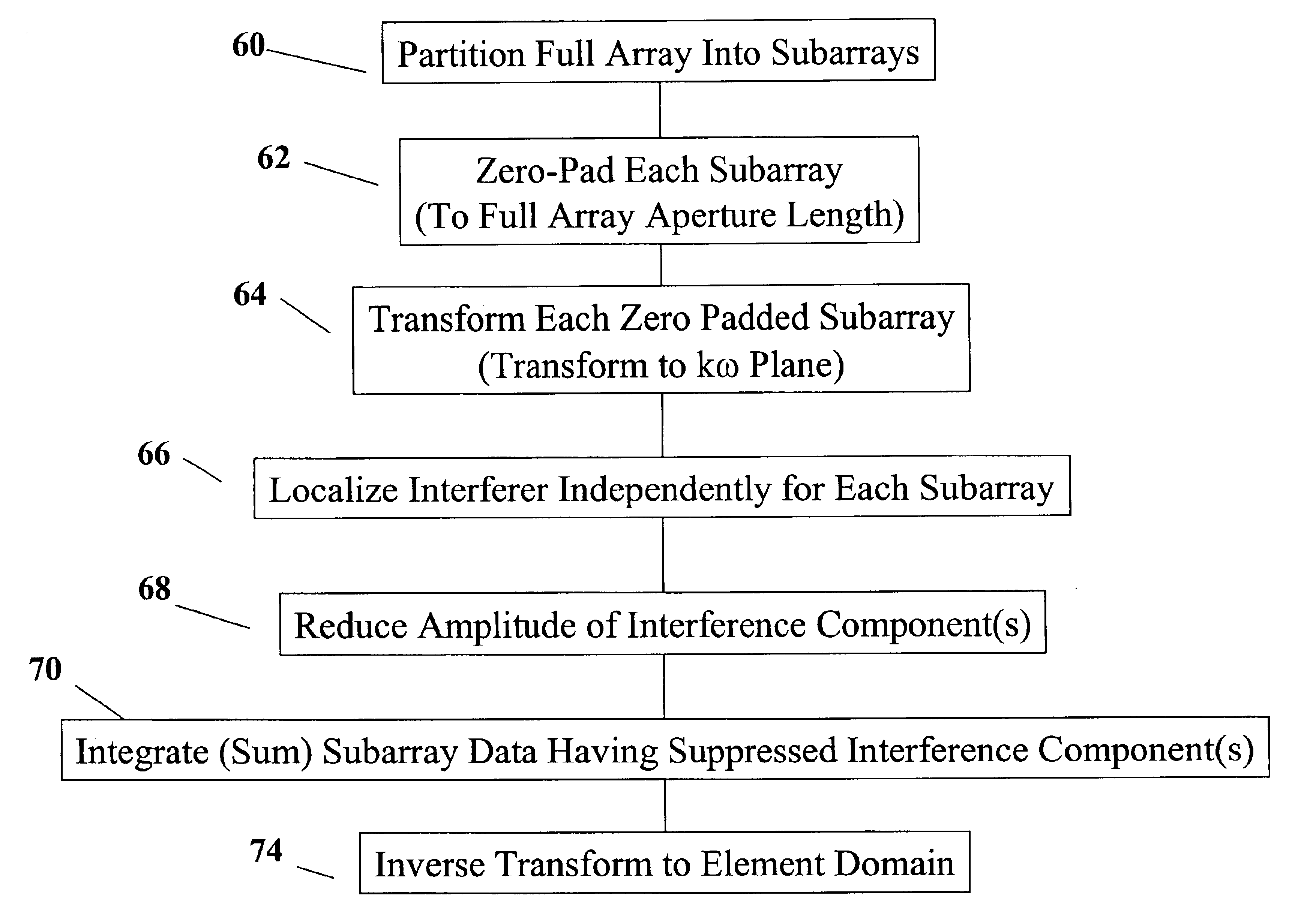
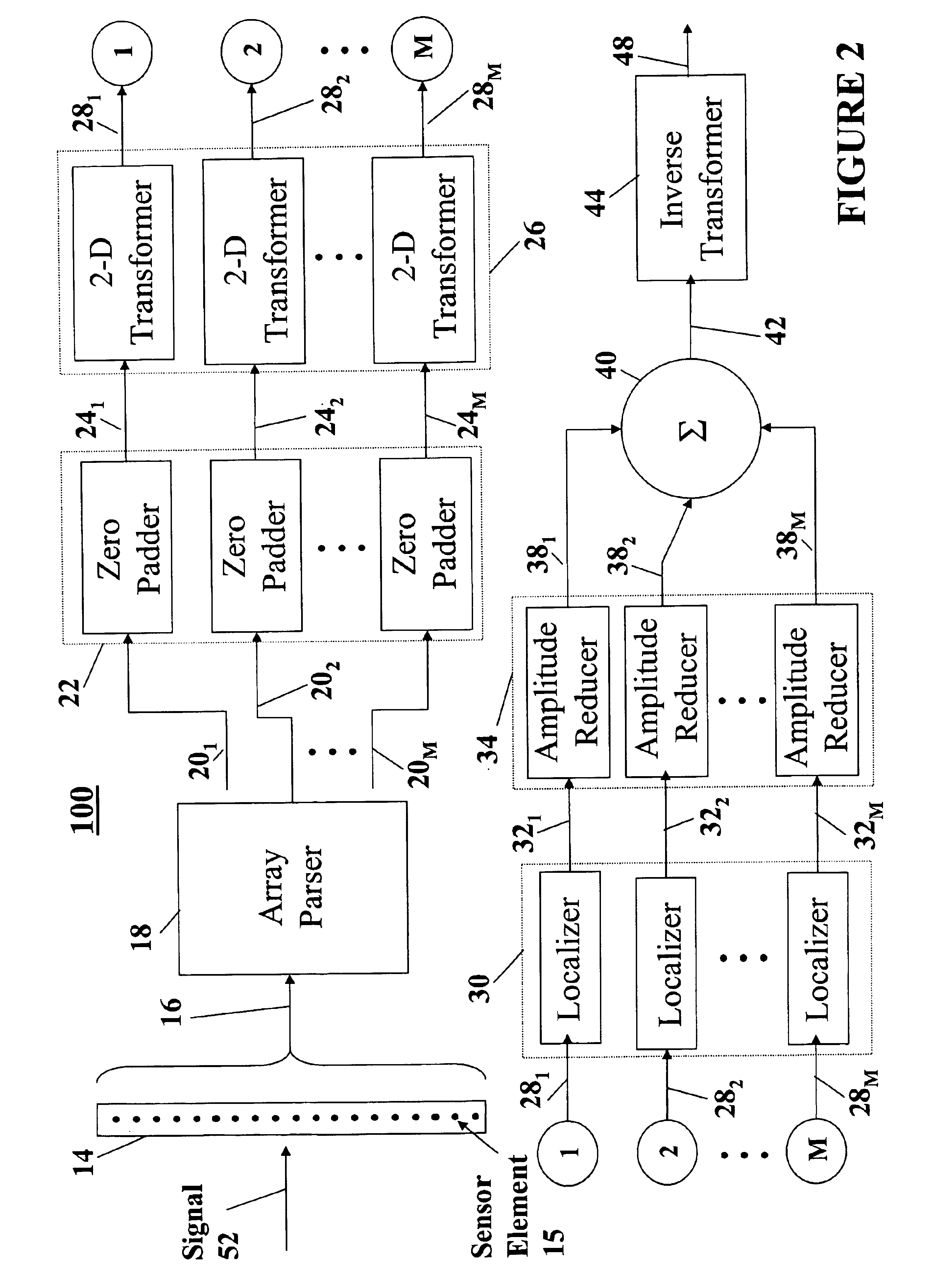
In one embodiment, an apparatus for suppressing at least one interference component of a signal received by an array of signal receivers includes an array parser, a zero padder, a two-dimensional transformer, a localizer, an integrator, and an inverse transformer. The array parser parses the array into a plurality of subarrays. The zero padder zero pads data provided by each of the plurality of subarrays. The two-dimensional transformer performs a two-dimensional transform on the data for each of the plurality of subarrays. The localizer localizes a source of each of the at least one interference component for each of the plurality of subarrays and provides a respective plurality of processed subarray signals. The integra...

Problems solved by technology

However, factors such as array motion, uncertainty of the location of elements in the array, uncertainty of the orientation of the array, and environmental affects such as multipath phenomena, produce errors in phase shift estimations.
Errors in phase shift estimation can result in notches being formed that are too wide, thus suppressing energy other than interference energy.
This is of particular concern when the interferer is spatially close enough to the target of interest such that the notch actually suppresses the desired signal provided by the target of interest.
Also, errors in the phase shift estimation can result in notches that are not steered to the proper direction.

Method used


Image

  • Data adaptive interference suppression
  • Data adaptive interference suppression
  • Data adaptive interference suppression

Examples


Embodiment Construction

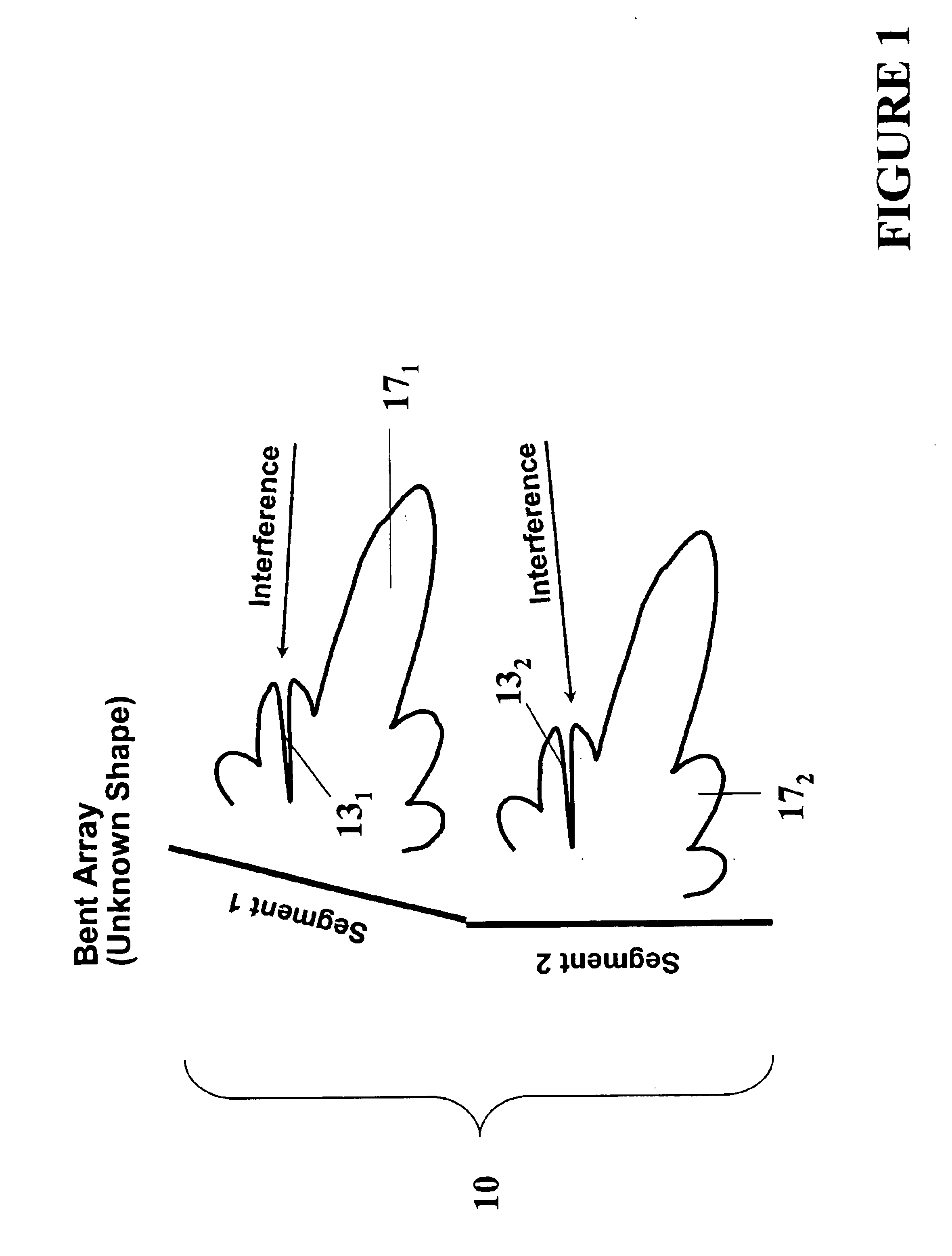
As described in more detail herein, signals received by an array of sensor elements are processed to suppress interference contained therein. Referring to FIG. 1, there is shown a linear array 10 having misaligned array segments denoted as segment 1 and segment 2. The relative orientation of segment 1 and segment 2 is unknown. Such an array may comprise a towed array of sonar sensors typically housed in a protective sheath or cable and separated a predetermined distance from one another in a linear fashion. A first end of the cable is coupled to signal processing circuitry at a first node that is typically on board a tow platform, such as a ship. The second end (i.e. “wet end”) of the array cable extends out from the tow platform in to the water medium. As applied to undersea applications, ownship course changes, environmental forces or other factors tend to impact portions of the array such that relative portions or segments of the array become misaligned. In accordance with an emb...


PUM


Abstract

A technique for suppressing interference with unknown phase shifts received by an array of sensor elements partitions the array into a plurality of subarrays. Each subarray is processed independently to suppress the interference. Next, the resulting data from each subarray are summed together. This summed data, which effectively represents data provided by the full array with interference suppressed, may be utilized to detect and / or localize a target of interest. Each subarray is processed independently of all other subarrays. No cross-subarray processing is required. This technique is applicable to linear arrays, multi-line arrays, planar arrays, cylindrical arrays, conformal arrays, and spherical arrays. Applicable sensors include acoustic sensors (e.g., sonar, ultrasonic), electromagnetic sensors (e.g. radar), and optical sensors (e.g., infrared, ultraviolet, visible light).

Description

FIELD OF THE INVENTIONThe present invention is generally related to signal processing, and more specifically related to reducing interference signals received by an array of elements.BACKGROUNDAn object of typical sonar and radar systems is to localize a target of interest. Localization typically comprises determining a range and bearing to the target of interest Strong interferers can mask signals representing these targets. Examples of interferers include surface shipping traffic for sonar systems and jammers for radar systems.To suppress interference, systems have utilized arrays of sensor elements. Given knowledge of the exact phase shifts with respect to the signals received by the elements of the array, notches can be formed in beam patterns and steered in the direction of the interferer to suppress, and even cancel the interfering energy. In practice, these phase shifts are estimated. However, factors such as array motion, uncertainty of the location of elements in the array,...

Claims


Application Information

Patent Timeline
IPC IPC(8): G01S3/801G01S3/00G01S3/40G01S3/785G01S3/805
CPCG01S3/40G01S3/8055G01S3/785Y10S367/901
Inventor BARNARD, THOMAS J.
Owner LOCKHEED MARTIN CORP
Learn More