
Delivery clamp module of media dispenser and control method thereof

a technology of clamp module and media dispenser, which is applied in the direction of transportation and packaging, thin material handling, and delivery of articles, etc., can solve the problems of difficult removal, difficult repair, and difficulty in the prior art, and achieve the general configuration of the present invention relatively simplified

Active Publication Date: 2009-06-23
ATEC AP CO LTD
View PDF8 Cites 2 Cited by
  • Summary
  • Abstract
  • Description
  • Claims
  • Application Information

AI Technical Summary

Benefits of technology

[0013]Another object of the present invention is to provide a media dispenser wherein a portion through which media are delivered to a customer can be freely set.
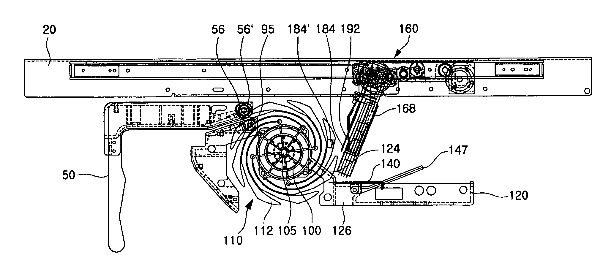
[0019]The clamp base is formed with a plurality of interference preventing slots parallel with each other to be opened toward its front end, so that the clamp base is prevented from interfering with peripheral components upon rotation thereof.
[0029]According to another aspect of the present invention, there is provided a method for controlling the delivery clamp module of the media dispenser when media are fed by using the delivery clamp module, comprising the steps of: positioning the clamp base to support a side of the media which are vertically erected on an upper portion of a stacking module and stacked on the stacking module; clamping the media to the clamp base by means of push fingers by rotating the clamp arm in a direction of the clamp base in a state where the media are completely stacked; retracting the delivery tray with the media clamped therein and simultaneously rotating the clamp base to a state where the clamp base is parallel with the delivery tray; and moving the media to a position where a customer may take out the media by moving the delivery tray.
[0031]According to the delivery clamp module of the media dispenser of the present invention so constructed, the media stacked on the stacking module are clamped directly by the delivery clamp module, and delivered to the customer or rejected if the customer has not yet taken out the media. Thus, there is an advantage in that the general configuration of the present invention is relatively simplified.
[0032]In addition, the media can be always securely pushed to the clamp base and clamped by an elastic force of the push fingers of the clamp arm regardless of the number of the media. Further, there is an advantage in that the one media sensor can sense whether or not the media are clamped, taken out, and the like by installing the media sensor and the reflecting member to the clamp base and the clamp arm, respectively.

Problems solved by technology

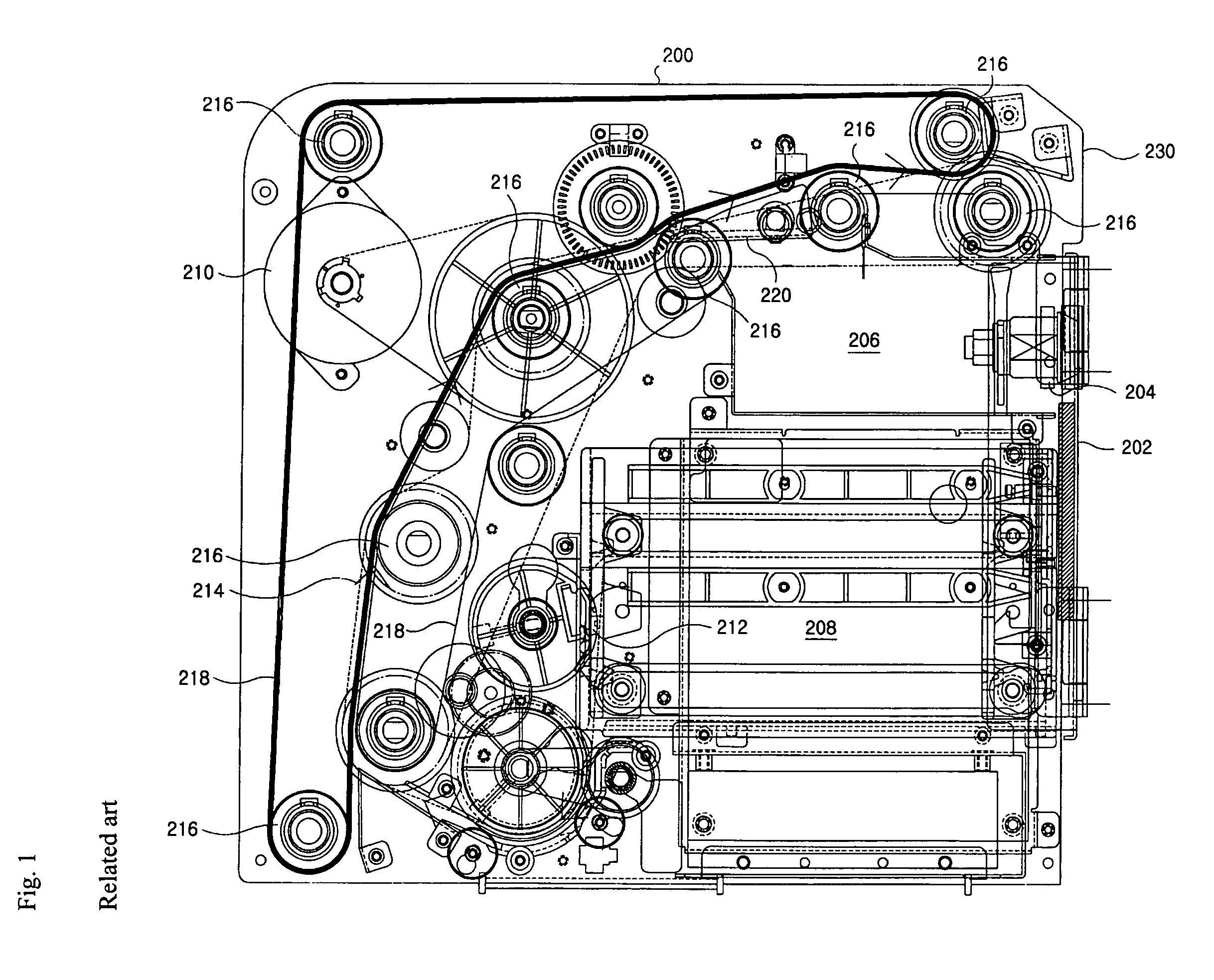
However, such a prior art has some problems as follows.
Therefore, if the media are jammed on the feeding path 214, it is very difficult to remove them.
In particular, if the components constituting the feeding path 214, especially, the components provided between the guide plates 200, are damaged, it is very difficult to repair them.
Thus, a large number of the media are not closely stacked and thus become large in volume, so that it is very inconvenient that the customer takes them by hand.
Furthermore, when the customer did not take out the media, there is a problem in that a reject box for receiving the rejected media should be adjacent to the position, where the customer takes out the media.

Method used


Image

  • Delivery clamp module of media dispenser and control method thereof
  • Delivery clamp module of media dispenser and control method thereof
  • Delivery clamp module of media dispenser and control method thereof

Examples


Embodiment Construction

[0050]Hereinafter, a preferred embodiment of a delivery clamp module of a media dispenser according to the present invention will be described in detail with reference to the accompanying drawings.

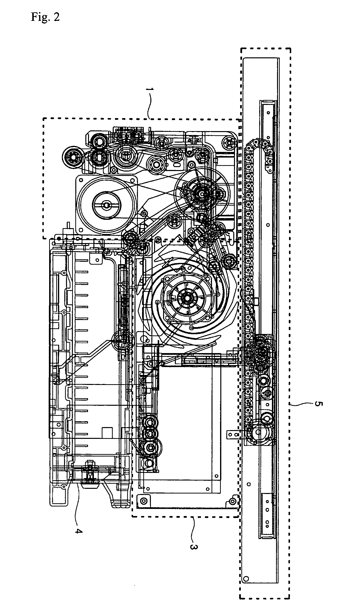
[0051]First, FIG. 2 is a side view generally showing a media dispenser where a delivery clamp module of an embodiment according to the present invention is employed. FIG. 3 is a schematic perspective view showing a major portion of the media dispenser according to the present invention. Referring to the figures, a media dispenser of the embodiment according to the present invention comprises a delivery module 1, a stacking module 3, and a delivery clamp module 5. The delivery module 1 serves to separate numbers of media from a media box (not shown), in which the media are stored, one by one and feed the media fed through a feed module (not shown) to a predetermined position. While feeding the media, the delivery module 1 also serves to divide the media into ones to be rejected and the othe...


PUM

PropertyMeasurementUnit
driving forceaaaaaaaaaa
elastic forceaaaaaaaaaa
magnetic forceaaaaaaaaaa

Abstract

The present invention relates to a delivery clamp module and a control method thereof. According to the present invention, there is provided a delivery clamp module. The delivery clamp module comprises a clamp guide with a movement guide rail included therein; a delivery tray movable along the rail of the clamp guide by means of a driving force of a tray delivery motor; a clamp base rotatably connected to a front end of the delivery tray through a connecting arm, rotated within a predetermined angular range by a base rotating motor, and supporting a surface of the stacked media; and a clamp arm installed on the clamp base, including push fingers for pushing the media onto the clamp base by an elastic force, and rotated with respect to the clamp base within a predetermined angular range by an arm rotating motor. According to the present invention so constructed, since the media stacked on the stacking module are clamped directly by the delivery clamp module, and delivered to the customer or rejected if the customer did not take out the media, there is an advantage in that the general configuration of the present invention is relatively simplified. In addition, the media can be always securely pushed to the clamp base and clamped by an elastic force of the push finger of the clamp arm regardless of the number of the media. Further, there is an advantage in that it is possible for a media sensor to sense whether or not the media are clamped, taken out, and the like by installing the media sensor and a reflecting member to the clamp base and the clamp arm.

Description

BACKGROUND OF THE INVENTION[0001]1. Field of Invention The present invention relates to a media dispenser, and more particularly, to a delivery clamp module which delivers a customer's desired number of media to the customer and a control method thereof.[0002]2. Description of the Prior Art[0003]FIG. 1 shows the constitution of a prior art media dispenser. According to the figure, various components for feeding media are provided between two guide plates 200 spaced apart by a predetermined interval from each other. A front surface of the media dispenser corresponding to an end of the guide plates 200 is provided with a door 202 for selectively opening or closing a predetermined space formed between the guide plates 200. The door 202 is installed to the guide plates 200 to be opened or closed about a hinge. Reference numeral 204 designates a locking member for keeping the door 202 closed.[0004]In the meantime, a reject box 206 for collecting abnormal media is mounted in the space bet...

Claims


Application Information

Patent Timeline
Patent Type & Authority Patents(United States)
IPC IPC(8): B65H29/00
CPCB65H29/40B65H31/06B65H31/3045B65H2301/42146B65H2301/42242B65H2405/51B65H2405/52B65H2408/13B65H2511/216B65H2513/42B65H2701/1912
Inventor CHOI, WOON-YONG
Owner ATEC AP CO LTD
Learn More