Apparatus for ion implantation

Inactive Publication Date: 2005-03-15
APPLIED MATERIALS INC
View PDF8 Cites 16 Cited by
  • Summary
  • Abstract
  • Description
  • Claims
  • Application Information

AI Technical Summary

Benefits of technology

An object of the present invention is to provide an ion implantation apparatus that can reduce such metal contamination.
In this structure, the beam guide section for the ions generated in the ion source section to pass toward the ion implantation section is provided with the charged particle generator for generating the charged particles having the opposite charge to that of the ions. Therefore, this charged particle generator also generates contaminant particles of contaminating matter for the substrate. However, since the shield section located between the opening of the introducing section and the outlet aperture is provided inside the guide tube, it can block paths of flight of contaminant particles jumping out through the opening of the internal wall of the guide tube and reaching the substrate.
With provision of this shield surface, it blocks paths of contaminant particles jumping out through the opening of the internal wall of the guide tube and directly arriving at the substrate.

Problems solved by technology

If such metal particles reach the substrate, they will cause an unwanted effect on devices to be formed on the substrate in many cases.
Therefore, this charged particle generator also generates contaminant particles of contaminating matter for the substrate.
However, since the shield section located between the opening of the introducing section and the outlet aperture is provided inside the guide tube, it can block paths of flight of contaminant particles jumping out through the opening of the internal wall of the guide tube and reaching the substrate.

Method used


Image

  • Apparatus for ion implantation
  • Apparatus for ion implantation
  • Apparatus for ion implantation

Examples


Embodiment Construction

A preferred embodiment of the present invention will be described hereinafter with reference to the drawings. The same portions will be denoted by the same reference symbols and redundant description will be omitted, as much as possible.

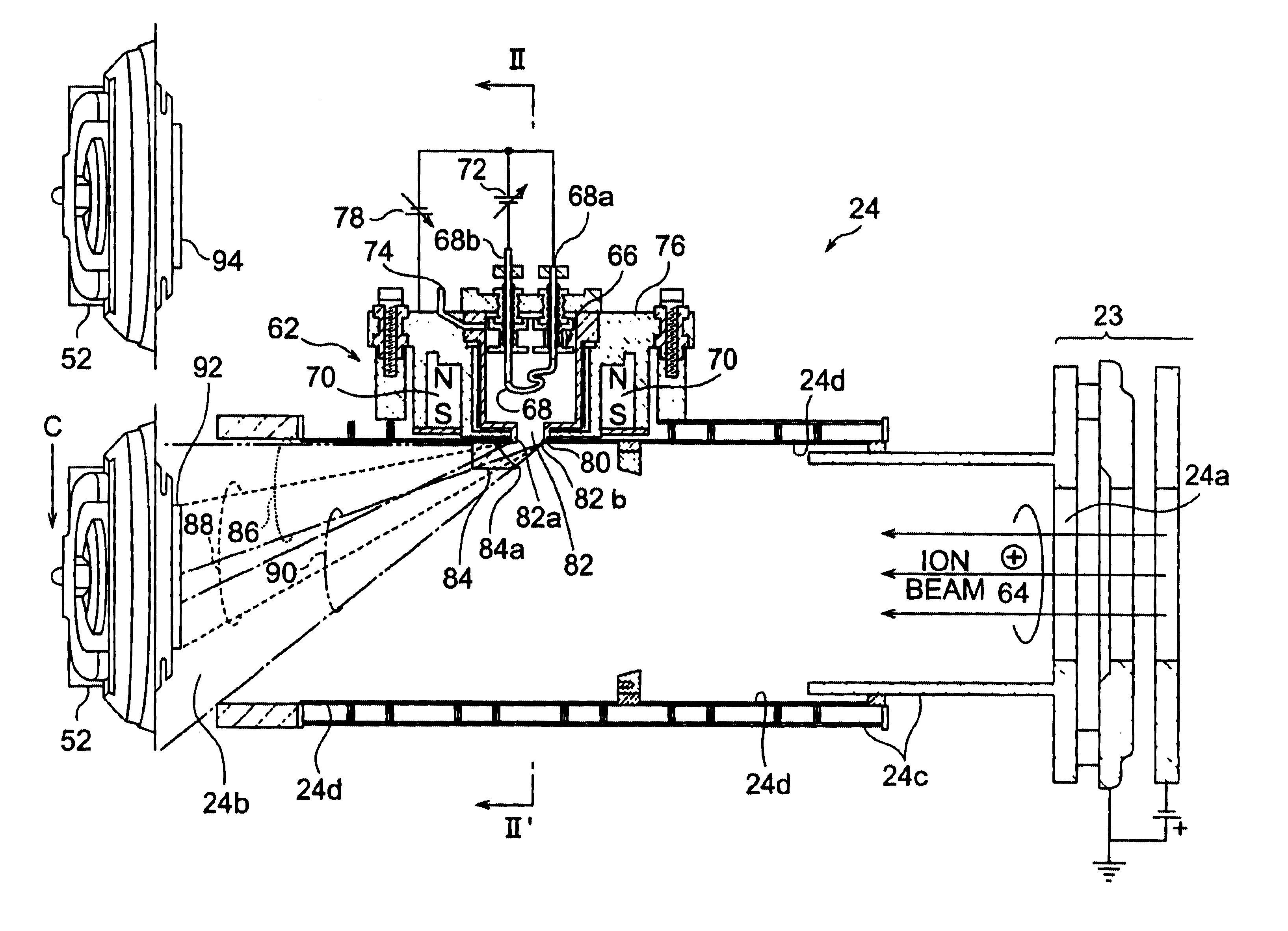
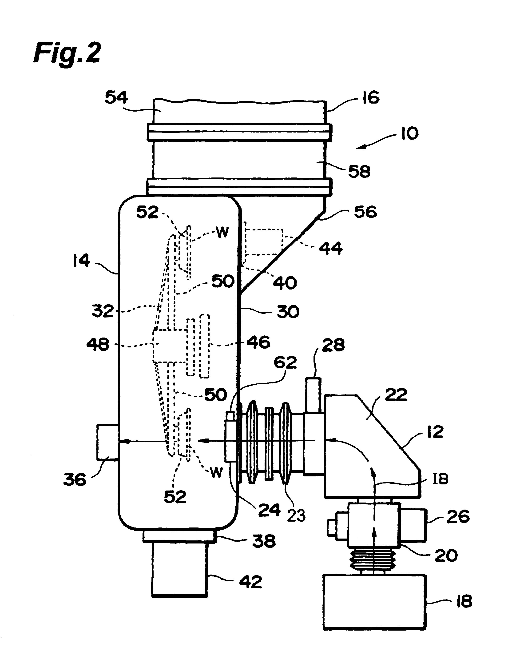
The ion implantation apparatus 10 according to the embodiment of the present invention will be described referring to FIG. 1 and FIG. 2. FIG. 1 is an exploded perspective view to show the preferred embodiment of the ion implantation apparatus according to the present invention. FIG. 2 is a schematic structural diagram of the ion implantation apparatus of the present embodiment.

Referring to FIG. 1 and FIG. 2, the ion implantation apparatus 10 is mainly comprised of an ion source section 12, an ion implantation section 14, and a beam guide section 24.

The ion source section 12 generates ions to form an ion beam (IB). Wafers (substrates) W are placed in the ion implantation section 14, and the ions generated in the ion source section 12 are implanted in ...


PUM

PropertyMeasurementUnit
Shapeaaaaaaaaaa

Abstract

An ion implantation apparatus comprises an ion source section (18) for generating ions; an ion implantation section (14) for implanting the ions generated in the ion source section (18), in a substrate (92); a charged particle generator (62) for generating charged particles having a charge opposite to that of the ions; a beam guide section (24) having an inlet aperture (24a) for accepting the ions from the ion source section (18), an outlet aperture (24b) for delivering the ions into the ion implantation section (18), a guide tube (24c) extending from the inlet aperture (24a) to the outlet aperture (24b), and an introducing section (80) having an opening (82) thereof in an internal surface (24d) of the guide tube (24c), for introducing the charged particles from the charged particle generator (62) into the guide tube (24c); and a shield section (84) located between the opening (82) of the introducing section (80) and the outlet aperture (24b) inside the guide tube (24c). A shield surface (84a) of the shield section (84) blocks the charged particles' reaching the wafer.

Description

TECHNICAL FIELDThe present invention relates to ion implantation apparatus and, more particularly, to ion implantation apparatus that can prevent a substrate from being contaminated by contaminant particles from a charged particle generator.BACKGROUND ARTLarge-current ion implantation apparatus performs ion implantation with an ion beam having a large current value in order to introduce a number of ions per unit time into a substrate. For this reason, the substrate itself is gradually charged up during execution of the ion implantation. If this charge build-up results in discharge, the substrate can be damaged by the discharge. In order to avoid such an accident, a charge neutralizer is used to prevent the charge build-up on the substrate. The charge neutralizer generates electrons for relieving the damage due to the charge of the substrate, whereby the negative charge of the electrons neutralizes the positive charge of ions to be implanted.DISCLOSURE OF THE INVENTIONHowever, the ch...

Claims


Application Information

Patent Timeline
IPC IPC(8): H01J37/02H01J37/317C23C14/48H01L21/265
CPCH01J37/026H01J37/3171H01J2237/022H01J2237/0041H01J37/30
Inventor ITO, HIROYUKIASECHI, HIROSHI
Owner APPLIED MATERIALS INC
Why Eureka
Try Eureka