
Heating apparatus and heating stabilization device in thereof

a technology of stabilizing device and heating apparatus, which is applied in the direction of electric/magnetic/electromagnetic heating, electrographic process, instruments, etc., can solve the problems of low energy efficiency, difficult to realize the pattern, and concerns regarding safety, so as to prevent excessive frying and solidification of food, prevent excessive frying and degrade in quality

Inactive Publication Date: 2005-03-15
AJINOMOTO CO INC
View PDF2 Cites 6 Cited by
  • Summary
  • Abstract
  • Description
  • Claims
  • Application Information

AI Technical Summary

Benefits of technology

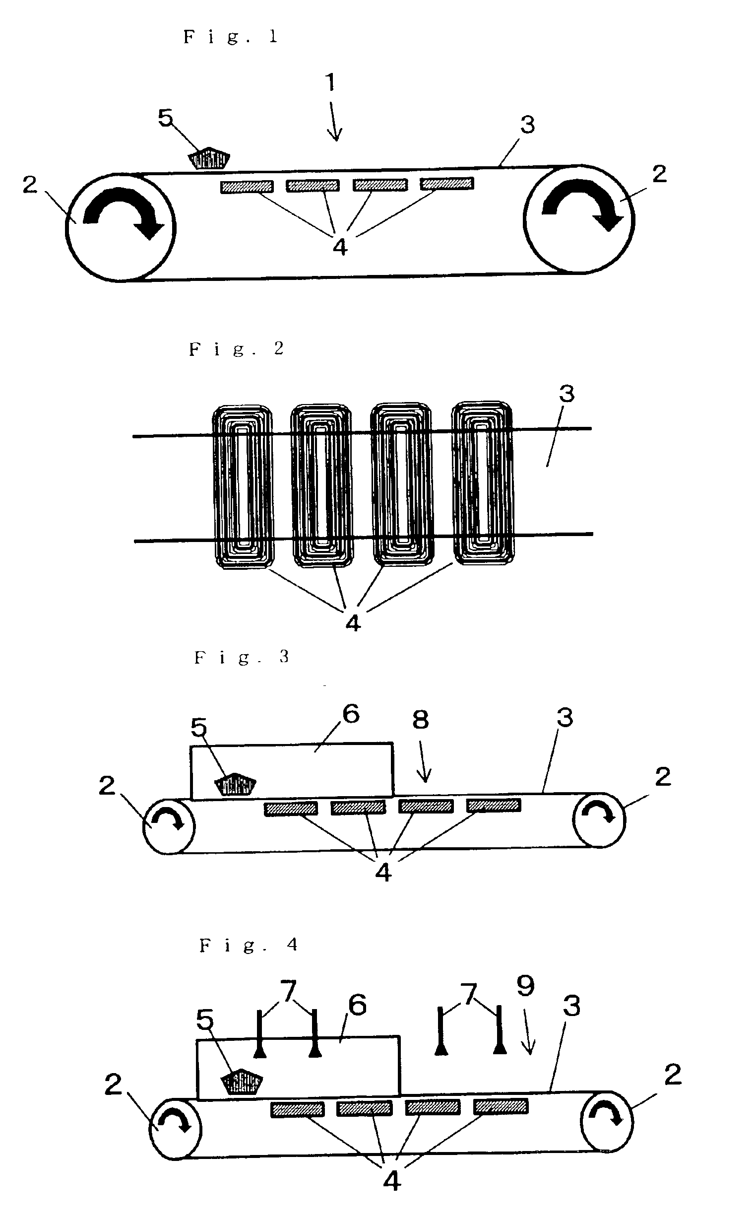
The length of the straight portions of each induction heating coil in the width direction of the steel belt can be greater than the width of part of the steel belt used for uniform heating of objects. Where the temperature profile along a line traversing the steel belt in the width direction has a large variation, a high-temperature portion and a low-temperature portion of the belt may have a large difference in the amount of expansion and thereby distort the top part of the steel belt. The distortion makes the distance between the top part of the steel belt and an induction heating coil deviate from the predetermined distance. The induction heating by the coil that is not separated from top part of the steel belt by the predetermined distance increases the variation of the temperature profile and hence increases the distortion.
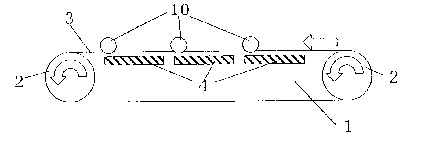
The rollers can be supported by a variety of methods. A preferred method is to connect and fix a shaft to portions of the body of the heating apparatus that are located outside the top part of the steel belt. As for a vertical elevation of the rollers, it is preferable that the rollers be disposed such that the bottoms of the respective rollers are in contact with the top surface of the top part of the steel belt when a heating operation is not performed. However, the rollers may be disposed above or below the above-discussed position depending on how the top part of the steel belt expands when a heating operation is performed. Where the rollers are disposed below the above-discussed position, the exertion of excessive stress on the top part of the steel belt can be avoided.

Problems solved by technology

However, problems with these apparatuses include low energy efficiency, and concerns regarding safety due to use of fire.
However, even if a swing pattern for attaining uniform heating is calculated, it is difficult to realize the pattern by reciprocating the swings with an air cylinder and a cam or the like.
As a result, uniform heating cannot be attained without using an expensive system including a combination of thermography, a computer, a servo motor, etc.
However, where a steel belt is heated by induction heating, if a portion of the steel belt is moved, the heating efficiency is lowered to a larger extent, such that the portion is insufficiently heated.
The portion of the steel belt that has expanded and risen is heated incompletely and therefore objects of heating that are mounted thereon are not heated in a desired manner.
This problem occurs more frequently in the case of rapid heating or cooling.
Thus, a large temperature variation occurs near objects of heating.
As described above, in heating apparatuses in which a steel belt and induction heating coils are used in combination, particularly where the conveyer is longer than 5 m, heating is insufficient due to the rise of the steel belt that produces a non-uniform temperature profile for the steel belt.

Method used


Image

  • Heating apparatus and heating stabilization device in thereof
  • Heating apparatus and heating stabilization device in thereof
  • Heating apparatus and heating stabilization device in thereof

Examples


example 1

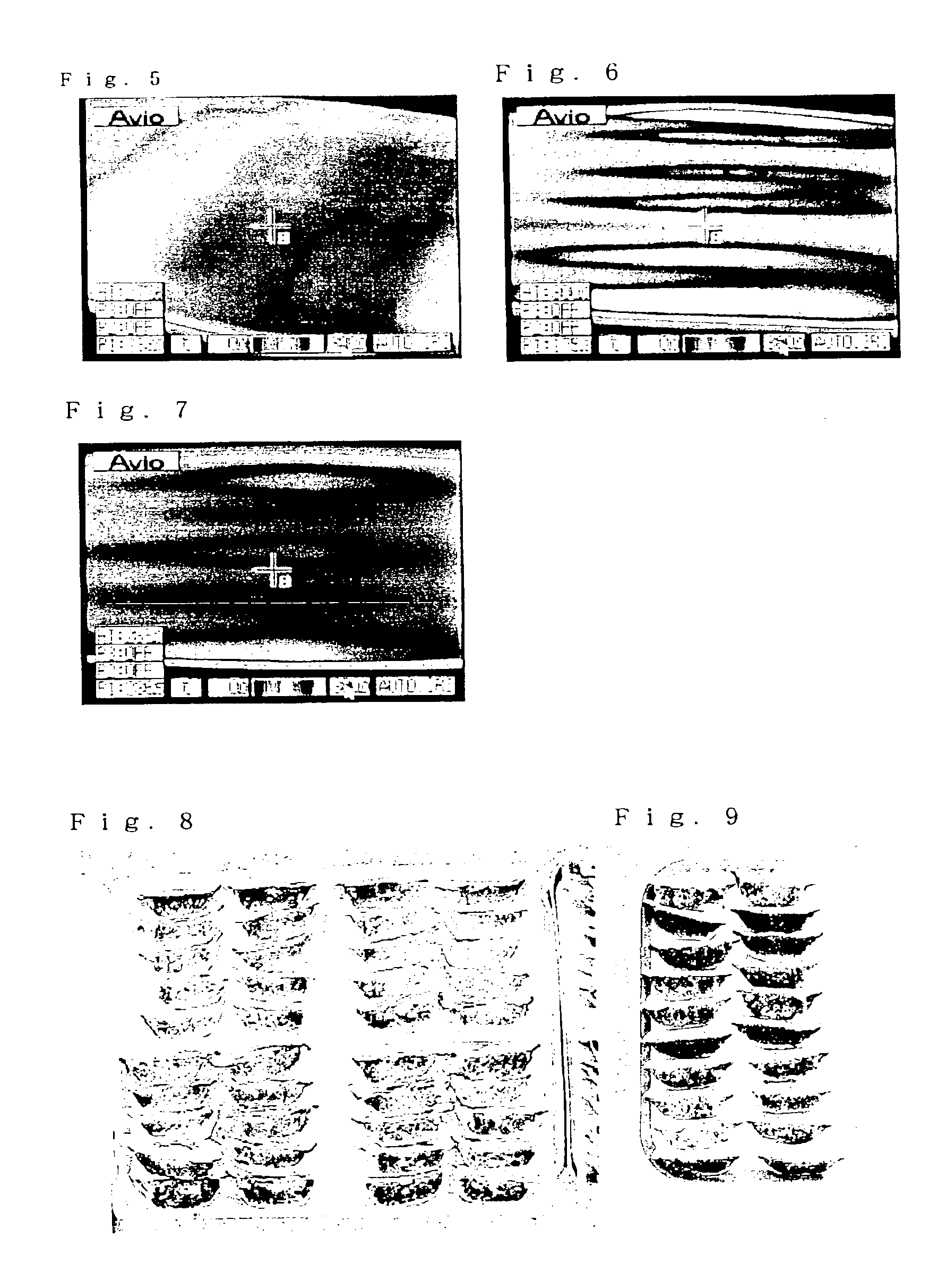
A temperature distribution of the top surface of the top part of a rotating steel belt was observed with a “Thermography” instrument (manufactured by Nippon Avionics Co., Ltd.) for a case in which a set of two elliptical coils having a relatively large major-axis-to-minor axis ratio was disposed such that the longitudinal directions of the respective coils were perpendicular to the belt moving direction as disclosed in the present invention, a case (Comparative Example 1) in which a set of three elliptical coils having a relatively large major-axis-to-minor axis ratio was disposed in such a manner that the longitudinal directions of the respective coils were parallel with the belt moving direction, and a case (Comparative Example 2) in which coils were arranged in the same manner as in Comparative Example 1 and were swung by an air cylinder.

In Comparative Example 1 (see FIG. 6), temperature unevenness was evident in the width direction of the steel belt. Temperature unevenness in th...

example 2

A carbon hardened steel belt of 1.2 mm in thickness, 1 m in width, and 60 m in length was formed into an endless belt, which was wound on two pulleys that are 800 mm in both diameter and width, to form a steel belt conveyer having a total length of about 30 m. Ten (10) induction heating coils, each capable of being housed in an 1 m square unit, were provided, and were arranged adjacent to an 11 m long, downstream portion of the top part of the steel belt under the bottom surface of the top part of the steel belt (distance: 10 mm). The coils were separated from each other by about 100 mm. Each coil unit was connected to an induction heating inverter of 30 kW. A temperature sensor was disposed under the bottom surface of a central portion, in the width direction, of the top part of the steel belt at a position 50 mm downstream from the coil unit. Each temperature sensor was disposed to be kept in contact with the bottom surface of the top part of the steel belt by a spring. A measurem...


PUM


Abstract

A heating apparatus includes a steel belt conveyer having a steel belt with a top part that transports and heats, and induction heating coils having an elliptical or a rectangular shape disposed under or over the top part of the steel belt such that the longitudinal direction of each of the induction heating coils forms an angle of 45° to 135° inclusive with the moving direction of the steel belt. A heating stabilization device can be used in such an apparatus. The heating stabilization device has one or a plurality of rollers that are brought into contact with the top surface of the top part of the steel belt so that the top part of the steel belt is prevented from rising during a heating operation.

Description

BACKGROUND OF THE INVENTIONCROSS-REFERENCE TO RELATED APPLICATIONSThe application claims priority to Japanese application nos. 203347 / 2001 and 101647 / 2002, the disclosures of which are incorporated by reference herein in their entirety.FIELD OF THE INVENTIONThe present invention relates to a heating apparatus that uses a steel belt as a heating body and enables uniform heating, the steel belt being heated by electromagnetic induction coils.DESCRIPTION OF THE BACKGROUNDIt is known to use steel belt conveyers for heating food continuously. Gas heating type steel belt ovens are used for baking confectioneries such as cookies and cream puffs. However, problems with these apparatuses include low energy efficiency, and concerns regarding safety due to use of fire.Japanese Patent Laid-Open No. 215605 / 1997 describes a heat-processing apparatus using a steel belt that is heated by induction heating coils. This invention remedies, to some extent, the above-discussed problems that are caused b...

Claims


Application Information

Patent Timeline
IPC IPC(8): H05B6/02
CPCH05B6/107
Inventor NISHINOMIYA, TAKESHIWAKABAYASHI, MAKOTOSADA, MORIHIROTAKAHASHI, HIROSHITERAZAKI, HIROFUMI
Owner AJINOMOTO CO INC
Learn More