Tank for draining a granular material/liquid mixture

a technology of granular material and liquid mixture, which is applied in the direction of sedimentation settling tanks, liquid displacement, separation processes, etc., can solve the problems of large overflow, large amount of granular material, and water flowing at high speed, and achieve uniform overflow

Inactive Publication Date: 2005-03-15
PAUL WURTH SA
View PDF14 Cites 3 Cited by
  • Summary
  • Abstract
  • Description
  • Claims
  • Application Information

AI Technical Summary

Benefits of technology

A tank for draining a granular material / liquid mixture according to the invention comprises a lower part and an upper part fitted with a lid. A device for separating the liquid and the granular material is arranged in the lower part. A device for removing excess liquid is arranged in the upper part. According to an important aspect of the invention, the device for removing excess liquid comprises a certain number of overflow sleeves passing through the lid. It will be appreciated that the overflow sleeves have, above the level of the lid, an overflow edge that is adjustable in height. The lid equipped with its overflow sleeves therefore constitutes an adjustable means of removing excess water. This possibility of individually adjusting the height of the overflow edge of each sleeve allows the sleeves to be set up in such a way as to obtain essentially equivalent overflows of liquid through each of them, thus ensuring uniform overflow. In general, to obtain uniform overflow, the overflow edges of the sleeves will preferably be adjusted so that they lie in one and the same horizontal plane. It will also be noted that the overflow sleeves make it possible to compensate for any inclination of the tank. A drainage tank according to the invention is particularly well suited to the drainage of a granular material / water mixture pumped from a granulating tank.

Problems solved by technology

One disadvantage with such a drainage tank is that, depending on the way in which the granular material spreads out within the tank, streams of water at higher speeds can form.
These streams of water at higher speeds cause greater overflowing at certain points around the periphery of the drainage tank, carrying with them fairly sizeable amounts of granular material.
The overflowing of the excess water is therefore not uniform around the entire periphery of the drainage tank.
In addition, the drainage tank is sometimes slightly inclined, and this further accentuates this problem of non-uniform overflow.

Method used


Image

  • Tank for draining a granular material/liquid mixture
  • Tank for draining a granular material/liquid mixture
  • Tank for draining a granular material/liquid mixture

Examples


Embodiment Construction

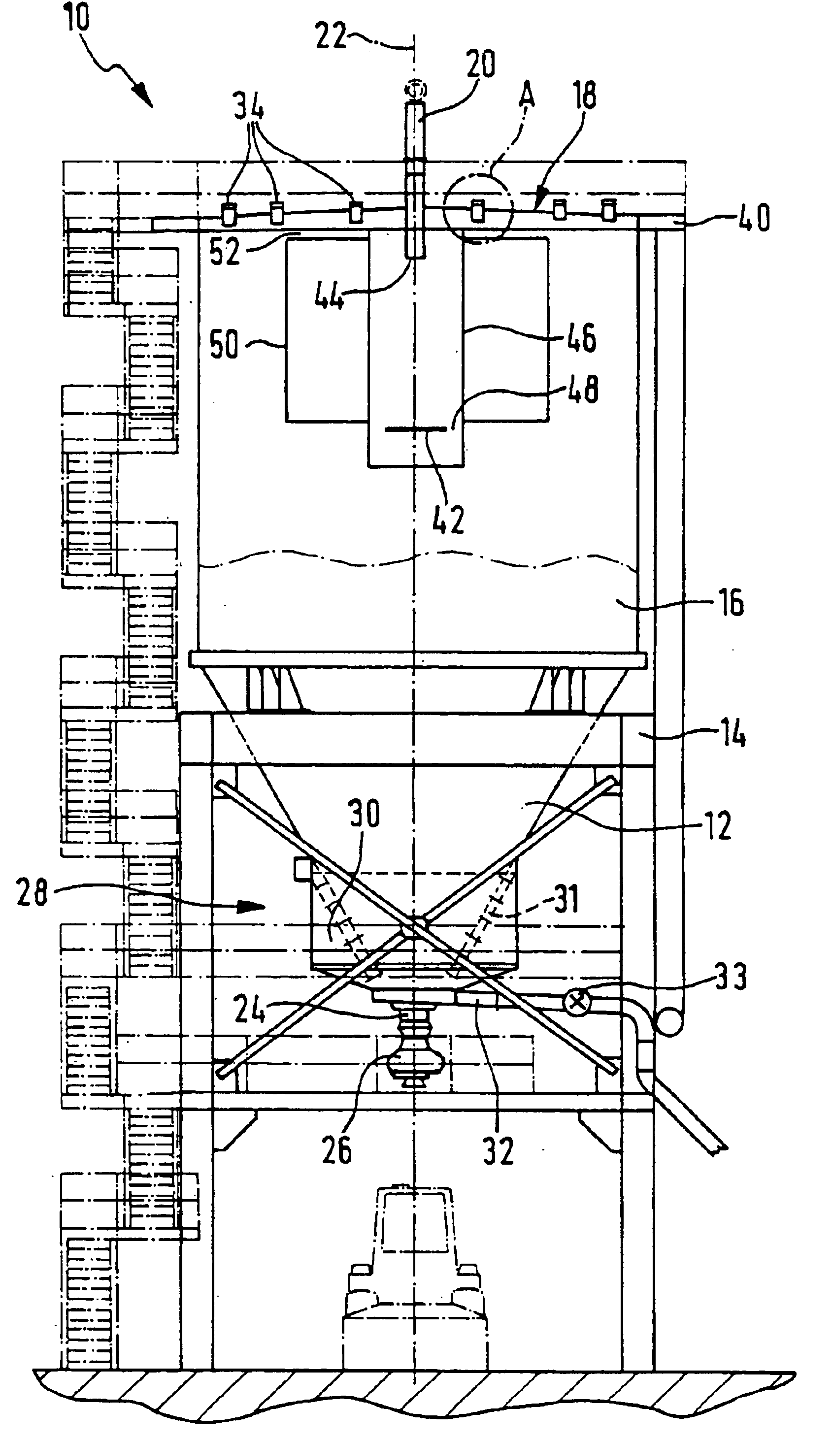
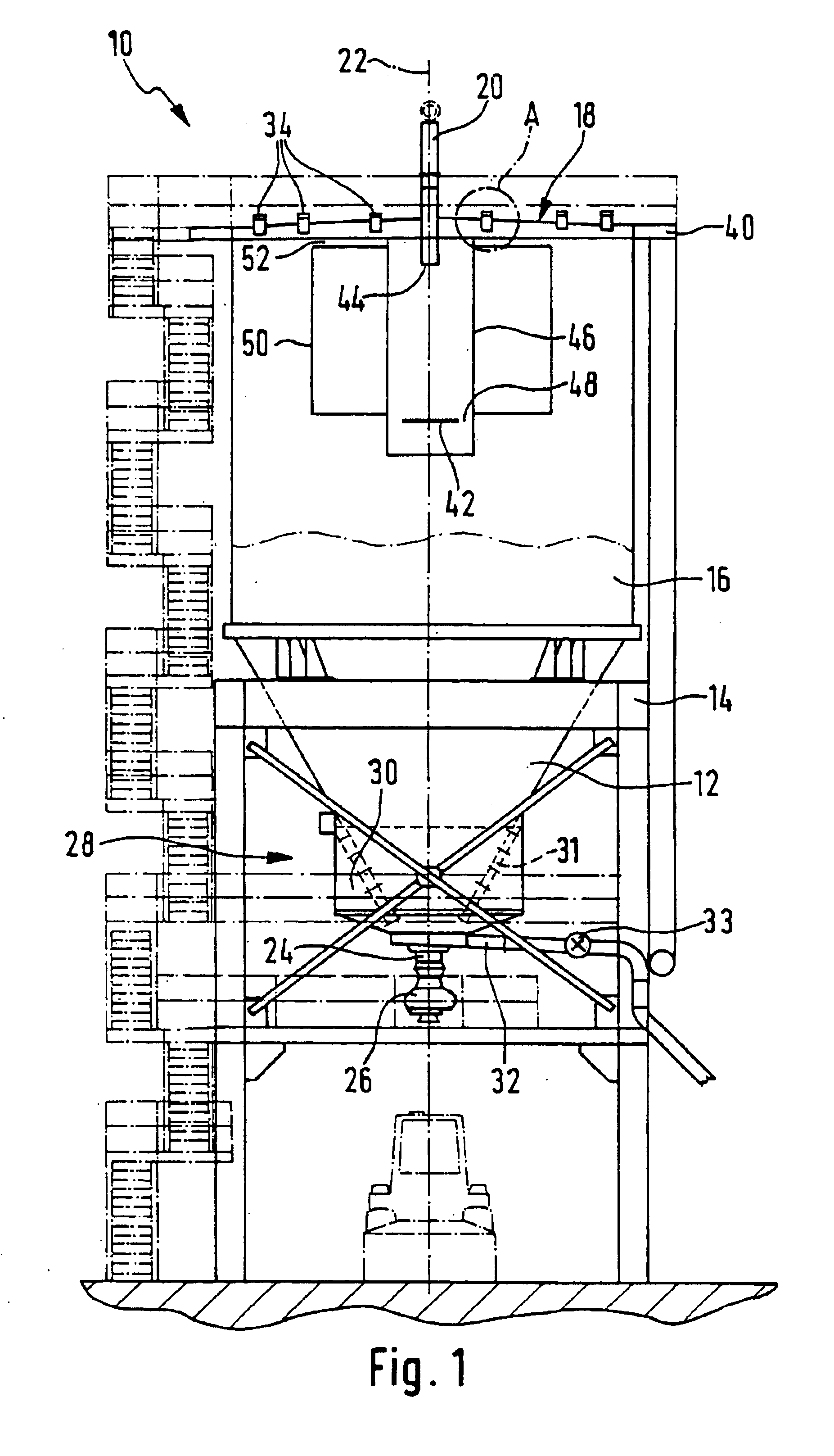
FIG. 1 illustrates a preferred embodiment of a drainage tank 10 in accordance with the invention. The drainage tank 10 comprises a lower part 12 of conical shape, supported in a framework 14, and a cylindrical upper part 16 surmounting the bottom part 12. The upper part 16 is equipped with a lid 18 covering the top of the drainage tank 10. The lid 18 has, passing through it, a filling line 20 which is used to fill the drainage tank 10 with a granular material / liquid mixture that is to be drained. This filling line 20 passes through the lid 18 in such a way as to be coaxial with a vertical central axis 22 of the drainage tank 10. The bottom part 12 ends in an outlet portion 24 equipped with a shut-off member 26. In the bottom part 12, upstream of the outlet portion 24, there is a device for separating the liquid and the granular material, generally labeled 28. The separating device 28 comprises an annular collection chamber 30 for the drained-off liquid and filtering surfaces 31 (sho...


PUM

PropertyMeasurementUnit
heightaaaaaaaaaa
diameteraaaaaaaaaa
diametersaaaaaaaaaa

Abstract

A drainage tank for granular material/liquid mixture includes a low part and a high part provided with a lid. A device for separating the liquid and the granular material is arranged in the low part. A device for evacuating excess liquid is arranged in the high part and includes a number of overflow sleeves passing through the lid. The overflow sleeves have, above the lid, an overflow edge that is adjustable in height.

Description

FIELD OF THE INVENTIONThe present invention relates to a tank for drainage a granular material / liquid mixture.BACKGROUND OF THE INVENTIONA granular material drainage tank is used in particular in a wet granulation plant in which a molten product is introduced into a powerful stream of water which solidifies, granulates and cools it. This operation is generally performed discontinuously in a granulating tank equipped for the injection of water of granulation. Once a batch of molten product has been poured into the granulation tank, and therefore granulated, the granular material / water mixture is pumped from the granulating tank to a drainage tank so that the granular material can be separated from the water of granulation.Such a drainage tank generally comprises a cylindrical upper part and a conical lower part which ends in an outlet portion equipped with a shut-off member. The conical lower part is also equipped, upstream of the shut-off member, with a device for separating the wat...

Claims


Application Information

Patent Timeline
Patent Type & Authority Patents(United States)
IPC IPC(8): B01D36/00B01D36/04B01D29/11B01D9/00B65D88/26B01D21/00B01D21/02B01D21/24B01D29/00B65D90/54
CPCB01D29/118B01D36/04B01D2201/48B01D2201/02
Inventor KERSCHENMEYER, GUYVAN HOOFF, WOLFGANGHARTZ, JEAN
Owner PAUL WURTH SA
Why Eureka
Try Eureka