
Method of setting self-pinned AP pinned layers with a canted field

a canted field and ap pinned technology, applied in nanoinformatics, special recording techniques, instruments, etc., can solve the problems of troublesome setting the proper polarity of the ap pinned layer next to the free layer, and achieve the effect of improving the uniaxial anisotropy field of magnetostriction, high magnetoresistive coefficient dr/r, and high magnetoresistive coefficien

Inactive Publication Date: 2005-03-15
HITACHI GLOBAL STORAGE TECH NETHERLANDS BV
View PDF9 Cites 21 Cited by
  • Summary
  • Abstract
  • Description
  • Claims
  • Application Information

AI Technical Summary

Benefits of technology

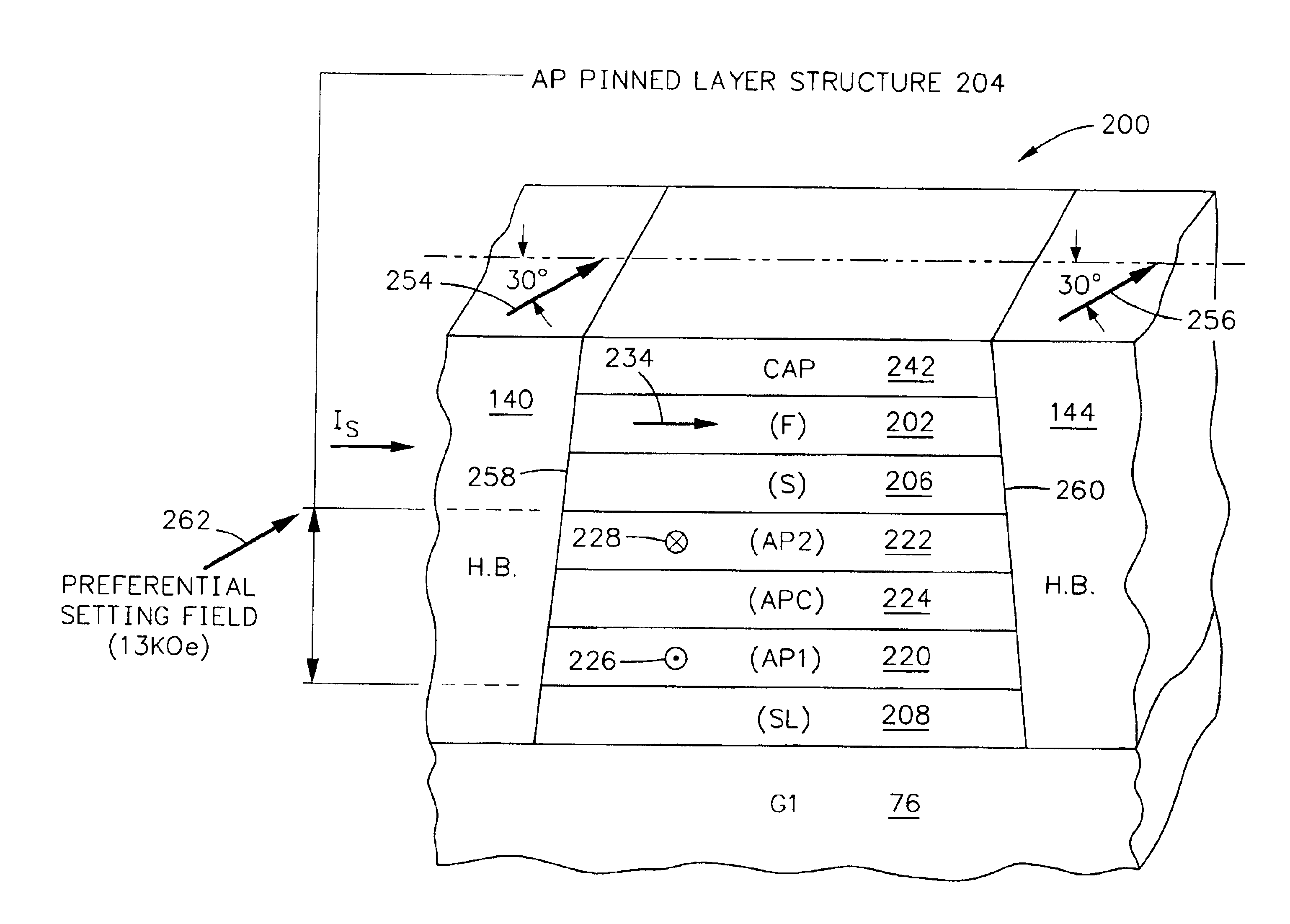
"The present invention provides a self-pinned antiparallel (AP) pinned layer structure without an AFM pinning layer. The AP pinned layers have uniaxial anisotropy fields that align with the ABS when a processing circuitry is designed. The invention achieves the proper polarity of the AP pinned layers by applying a canted magnetic field at an acute angle to the ABS. The invention also sets the easy axes of the magnetic moments of the AP pinned layers perpendicular to the ABS at the wafer level. The use of cobalt iron (CoFe) in the AP pinned layers with different iron (Fe) content in each layer improves the magnetostriction uniaxial anisotropy field while maintaining a high magnetoresistive coefficient dr / R. The invention provides a more efficient and effective method for aligning the magnetic moments of the AP pinned layers with the ABS."

Problems solved by technology

Setting the proper polarity of the AP pinned layer next to the free layer is troublesome when present prior art techniques are employed.

Method used


Image

  • Method of setting self-pinned AP pinned layers with a canted field
  • Method of setting self-pinned AP pinned layers with a canted field
  • Method of setting self-pinned AP pinned layers with a canted field

Examples


examples 1-5

were tested at the coupon level and Examples 1 and 2 were further tested at the row level. At the coupon level a single sensor is fabricated on a glass substrate and is not lapped to the ABS. Since lapping causes the aforementioned ABS compressive stress the ABS compressive stress due to lapping is not present at the coupon level. The row level is a row of read heads including their read sensors and is taken from a slider substrate where rows and columns of such read heads have been fabricated. After dicing the row of read heads from the slider substrate, the row is lapped to the ABS which causes the aforementioned compressive stress.

At the coupon level the magnetoresistive coefficient dr / R, the intrinsic uniaxial anisotropy field HKi, the magnetostriction λ (AP) of the AP pinned layers, the magnetostriction uniaxial anisotropy field HKλ, the resistance of the sensor RS and the magnetostriction of the free layer λ (FL) were determined and / or calculated. At the row level Examples 1 a...


PUM

PropertyMeasurementUnit
acute angleaaaaaaaaaa
magnetic momentaaaaaaaaaa

Abstract

A spin valve sensor in a read head has a spacer layer which is located between a self-pinned AP pinned layer structure and a free layer structure. The free layer structure is longitudinally stabilized by first and second hard bias layers which abut first and second side surfaces of the spin valve sensor. The AP pinned layer structure has an antiparallel coupling layer (APC) which is located between first and second AP pinned layers (AP1) and (AP2). The invention employs a preferential setting of the magnetic moments of the AP pinned layers by applying a field at an acute angle to the head surface in a plane parallel to the major planes of the layers of the sensor. The preferential setting sets a proper polarity of each AP pinned layer, which polarity conforms to processing circuitry employed with the spin valve sensor.

Description

BACKGROUND OF THE INVENTION1. Field of the InventionThe present invention relates to a method of setting self-pinned antiparallel (AP) pinned layers with a canted field and, more particularly, setting the orientation (polarity) of magnetic moments of such layers by canting a field at an acute angle to the air bearing surface (ABS) of a read head in a plane parallel to the major planes of the layers of the read head.2. Description of the Related ArtThe heart of a computer is a magnetic disk drive which includes a rotating magnetic disk, a slider that has write and read heads, a suspension arm above the rotating disk and an actuator arm. The suspension arm biases the slider into contact with the surface of the disk or parks the slider on a ramp when the disk is not rotating but, when the disk rotates, air is swirled by the rotating disk adjacent an air bearing surface (ABS) of the slider causing the slider to ride on an air bearing a slight distance from the surface of the rotating di...

Claims


Application Information

Patent Timeline
Patent Type & Authority Patents(United States)
IPC IPC(8): G11B5/39G11B5/00G11B5/31
CPCB82Y10/00B82Y25/00G11B5/3903G11B5/3909G11B5/3163G11B5/3932Y10T29/49027G11B2005/0016G11B2005/3996Y10T29/49043Y10T29/49021Y10T29/49032Y10T29/49044G11B2005/0008
Inventor GILL, HARDAYAL SINGHTRAN, ANDY CUONG
Owner HITACHI GLOBAL STORAGE TECH NETHERLANDS BV
Learn More