
Electrophoretic electronic displays with low-index films

a technology of electrophoretic display and low-index film, applied in the field of electrophoretic display, can solve the problems of undesirable optical cross-talk, certain optical inefficiencies, etc., and achieve the effects of improving yield, simplifying the construction process, and high reflective performan

Inactive Publication Date: 2005-03-08
E INK CORPORATION
View PDF326 Cites 486 Cited by
  • Summary
  • Abstract
  • Description
  • Claims
  • Application Information

AI Technical Summary

Benefits of technology

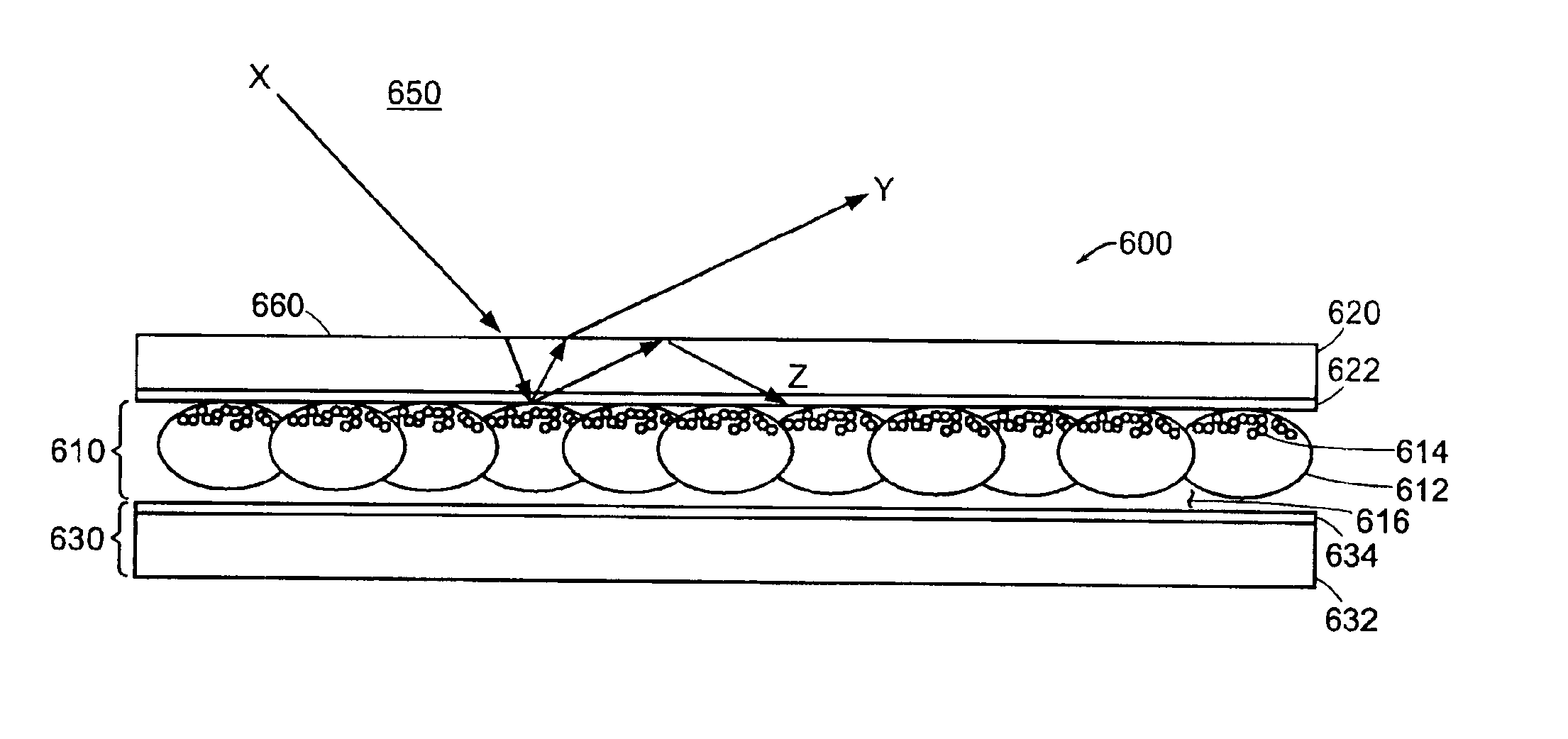
When the encapsulating structure is thin, its interface with the low-index refraction layer is close to the reflective portion of the display medium. As a result, when light from a spot on the reflective portion of the display medium, for example, part of a pixel, reaches the interface between the encapsulating structure and the low-index refraction layer, the portion of the light that gets internally reflected is more likely to bounce back onto a second spot proximate to the first spot. In an embodiment, the two spots are of the same pixel. As a result, more light gets “recycled” and eventually reaches an observer of the display. Moreover, optical cross-talk is reduced because the internal reflection is more localized.
The reflective particles belong to a display medium layer. The reflective particles can be a component of an unencapsulated display medium layer, and the material portion can assist containment of the particles. Such a material portion can be one or more layers, for example, a barrier layer, which can be flexible or rigid.
The method can include selecting a thickness of the material portion to cause most internally reflected scattered light to return to a same pixel.

Problems solved by technology

Certain optical inefficiencies exist, however, in the typical electrophoretic display.
Furthermore, re-scattering from neighboring pixels can cause undesirable optical cross-talk.

Method used


Image

  • Electrophoretic electronic displays with low-index films
  • Electrophoretic electronic displays with low-index films
  • Electrophoretic electronic displays with low-index films

Examples


Embodiment Construction

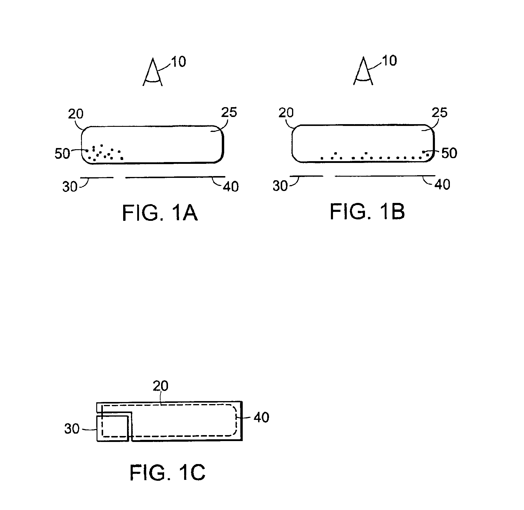
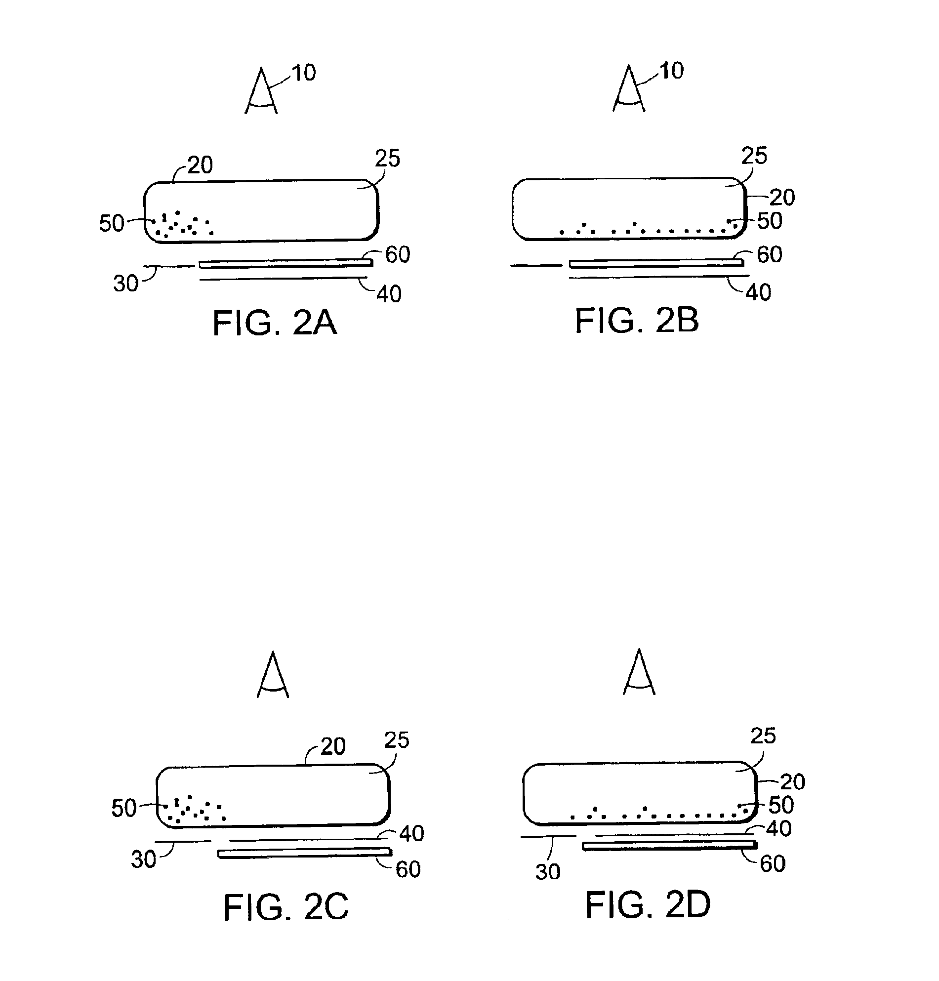
In the following embodiments of the invention, color electrophoretic displays are first described, with reference to FIGS. 1-16. Electrophoretic displays that include an optical biasing element are described, with reference to FIGS. 17-20. Illustrative embodiments of reflective displays that include a low refractive index (“low-index”) film to enhance the optical characteristics of the displays are described with reference to FIGS. 21-25. It is to be recognized that all of the electrophoretic displays described herein and illustrated in the figures may include a low-index film according to the present invention. Lastly, various embodiments of materials that may be included in an electrophoretic display medium of the present invention are further described.

An electronic ink is an optoelectronically active material which comprises at least two phases: an electrophoretic contrast medium phase and a coating / binding phase. The electrophoretic phase comprises, in some embodiments, a singl...


PUM

PropertyMeasurementUnit
Thicknessaaaaaaaaaa
Thicknessaaaaaaaaaa
Thicknessaaaaaaaaaa

Abstract

The invention features a reflective display device and a method of making a reflective display device that has reduced light loss and / or pixel cross talk due to internal reflection. The device includes a window layer, a plurality of reflective particles, a material portion disposed between the window layer and the plurality of reflective particles, and a refractive layer disposed between the window and the material portion. The plurality of reflective particles scatters light received from the ambient environment. The window layer has an index of refraction that is greater than an index of refraction of the ambient environment. The refractive layer has an index of refraction that is less than the index of refraction of the window layer and less than an index of refraction of the material portion.

Description

FIELD OF THE INVENTIONThe present invention relates to displays, and, in particular, to black and white and color electrophoretic displays.BACKGROUND OF THE INVENTIONElectrophoretic displays typically use reflective and absorbing pigments to produce optical performance that dramatically differs from traditional electronic displays. The white pigments, for example, used in the electrophoretic displays typically reflect light by a multiple scattering mechanism. The pigments thus are isotropic diffusers that create a Lambertian distribution of light reflected from a pigment surface. Electrophoretic displays thus typically have a light output intensity that approximates a Lambertian distribution. The output of reflective liquid crystal displays, in contrast, has an intensity that varies substantially with viewing direction.Certain optical inefficiencies exist, however, in the typical electrophoretic display. In a typical electrophoretic display, a sizable fraction of light scatters from...

Claims


Application Information

Patent Timeline
IPC IPC(8): G02F1/01G02F1/167G02F1/1334G02F1/13G02F1/1677
CPCG02F1/167G02F1/1334G02F1/1677
Inventor DUTHALER, GREGGPULLEN, ANTHONY
Owner E INK CORPORATION
Learn More